Lincoln Impinger Advantage Digital Series 1154-000-EA Service Manual
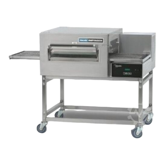
Impinger advantage digital series with push button controls
Hide thumbs
Also See for Impinger Advantage Digital Series 1154-000-EA:
- Service manual (36 pages) ,
- Installation and parts & service manual (36 pages)
Advertisement
Quick Links
SERVICE MANUAL
(INTERNATIONAL)
IMPINGER ADVANTAGE DIGITAL SERIES
MODEL 1154-000-EA, 1155-000-EA,
1164-000-EA
WITH PUSH BUTTON CONTROLS
Lincoln Foodservice Products, LLC
1111 North Hadley Road
Fort Wayne, Indiana 46804
United States of America
Phone : (800) 374-3004
U.S. Fax: (888) 790-8193 • Int'l Fax: (260) 436-0735
Technical Service Hot Line
(800) 678-9511
www.lincolnfp.com
1100ExAdDig
REV: 11/4/08
Advertisement

Subscribe to Our Youtube Channel
Related Manuals for Lincoln Impinger Advantage Digital Series 1154-000-EA


Summary of Contents for Lincoln Impinger Advantage Digital Series 1154-000-EA
- Page 1 (INTERNATIONAL) IMPINGER ADVANTAGE DIGITAL SERIES MODEL 1154-000-EA, 1155-000-EA, 1164-000-EA WITH PUSH BUTTON CONTROLS Lincoln Foodservice Products, LLC 1111 North Hadley Road Fort Wayne, Indiana 46804 United States of America Phone : (800) 374-3004 U.S. Fax: (888) 790-8193 • Int’l Fax: (260) 436-0735...
- Page 2 (opens at 140°F, 60°C), to the normally open double pole oven fan switch and to the cooling fan. Closing the oven fan switch supplies line voltage to the main fan motor. Closing the main fan switch also supplies voltage to the cooling fan, the primary of the control transformer, the conveyor motor, and the burner system.
-
Page 3: Power Supply
(closed by air pressure from the main fan) to the oven control. Line voltage is also supplied to the primary of the control transformer. Secondary voltage, 24VAC, is supplied to the oven control. The oven control is set to desired temperature. The thermocouple will provide varying millivolts to the oven control. -
Page 4: Schematic Diagram
SCHEMATIC DIAGRAM MODEL 1154-000-EA, 1155-000-EA SERIAL NUMBER 2038616 TO 2045407 Impinger II – Advantage Digital Service Manual - International... - Page 5 SCHEMATIC DIAGRAM MODEL 1154-000-EA, 1155-000-EA SERIAL NUMBER 2045408 AND ABOVE Impinger II – Advantage Digital Service Manual - International...
- Page 6 SCHEMATIC DIAGRAM MODEL 1164-000-EA SERIAL NUMBER 2038616 AND ABOVE Impinger II – Advantage Digital Service Manual - International...
- Page 7 SCHEMATIC DIAGRAM MODEL 1164-000-EA SERIAL NUMBER 2053336 AND ABOVE (RoHS Compliant) Impinger II – Advantage Digital Service Manual - International...
- Page 8 Check, replace if necessary. Check for voltage on both sides of switch. Terminals are normally closed. If open, reset and test oven for proper operation. If thermostat will not hold, and control box temperature is not exceeding 140°F (60°C), replace thermostat.
- Page 9 If these are okay, adjust air pressure switch or replace if necessary. Terminals are normally closed, opens at 660°F (350°C). If open, reset and test oven for proper operation. If thermostat will not hold for maximum oven temperature, and oven is not exceeding control setting, check for proper location of capillary bulb in its spring holder.
- Page 10 Also check flexible gas line connection. If not operating, refer to “Oven fan will not run”. Check air switch terminals for supply voltage to terminals C and NO. If voltage is present on one side only, check for air tube blockage or misalignment.
- Page 11 Check for supply voltage to the conveyor motor at terminal #6 to neutral. If no voltage is present, trace wiring back to the oven fan switch. If voltage is present, but the motor will not run, check the motor windings for opens or shorts.
- Page 12 25-100 Hz. If these readings are not achieved, replace conveyor motor. If the readings are achieved, proceed. If the hall effect sensor readings are correct, but there is no speed indicated on the display, replace the oven control TROUBLESHOOTING GUIDE IMPINGER II ADVANTAGE...
- Page 13 If these are okay, adjust air pressure switch or replace if necessary. Check for 24VAC supply to oven control. If no voltage is present, trace wiring back to control transformer. Check for supply voltage to oven control. If no voltage is present, trace wiring back to oven fan switch.
- Page 14 If the thermocouple checks good, but there is no supply voltage output to the mercury contactor, replace the oven control. If there is supply voltage output to the mercury contactor, proceed. Check for supply voltage to the contactor coil. If voltage...
- Page 15 Check for supply voltage to the conveyor motor at terminal #6 to neutral. If no voltage is present, trace wiring back to the oven fan switch. If voltage is present, but the motor will not run, check the motor windings for opens or shorts.
- Page 16 B. Remove motor cover from back of oven. C. Disconnect wiring and mark for reassembly. D. Remove bolts and slide back straight out of the oven. E. Loosen the bolt from fan hub and remove fan from motor shaft. NOTE: Measure distance from fan blade to rear wall assembly before removal to aid in reassembly.
- Page 17 A. Shut off power at main breaker. B. Remove conveyor and bottom finger assembly. C. Remove capillary bulb from bracket in oven chamber and pull capillary tube through tube into control box. D. Remove all wires and mark for reassembly.
- Page 18 The oven control must be set to the proper operating mode. Set the control as follows: With the oven power switch “off”, depress the “time” and “up” buttons and turn the oven “on”. Control will indicate ”Imp I or Imp II”. Release the buttons, The control will indicate “Temp to store”.
- Page 19 Reassemble in reverse order and check system operation. Check all gas line fitting for leaks. K. Adjust the gas manifold pressure on the gas valve. Refer to the specification plate on the oven for proper rating. GAS VALVE – REPLACEMENT (S/N 2045408 and Above) A.
- Page 20 TEMPERATURE REGULATION VALVE – REPLACEMENT A. Shut off power at main breaker. B. Shut off gas supply to the oven and disconnect the flexible gas line to oven. C. Remove control panel top and front cover. D. Remove bypass tube from burner manifold.
- Page 21 K. Reassemble control panel top and front cover. BEARING, CONVEYOR – REPLACEMENT A. Remove conveyor from oven and place on a flat work surface. B. Remove connecting links from conveyor belt. See Installation Operations manual for proper procedure. Remove conveyor belt from conveyor.
- Page 22 Bottom finger housing 369504 Top finger housing Columnating plate, see Installation & Operations manual 3695032 Top finger cover 369511 Oven top 369659 Conveyor hole cover (S/N 2052462 & Below) 370679 Conveyor hole cover (S/N 2052463 & Above) 371066 Baffle 369211...
- Page 23 Impinger II – Advantage Digital Service Manual - International...
- Page 24 Burner blower motor 369401 Air shutter assembly 369580 Gas valve Nat/LP S/N 2045407 and below 370400 Nat/LP S/N 2045408 and above 357067 Thermostat, hi-limit, oven cavity 369192 Capacitor 369771 Reset switch, ignition control 370359 Reversing switch, conveyor 353082 Ground lug...
- Page 25 Impinger II – Advantage Digital Service Manual - International...
- Page 26 369507 Thermostat, cooling fan 370383 Capacitor, conveyor motor (S/N 2052462 & Below) 370682 Capacitor, conveyor motor (S/N 2052463 & Above) 369192 Capacitor 369368 Thermostat, hi-limit, oven cavity 370359 Reversing switch, conveyor 353082 Ground lug 369698 Junction box 370117 Terminal block...
- Page 27 Impinger II – Advantage Digital Service Manual - International...
- Page 28 LETTER OVEN BACK ASSEMBLY PART NUMBER DESCRIPTION 369182 369899 Fan shroud 369655 Stand off 370164 Heating element 230 Volt Rear wall 369976 Gas ovens 369549 Electric ovens 369581 Motor mount 369196 Motor 369695 Bracket, motor 369033 Clamp, motor 369681 Cover, back...
- Page 29 Impinger II – Advantage Digital Service Manual - International...
- Page 30 LETTER Not Shown Not Shown CONVEYOR / DOOR PART NUMBER DESCRIPTION 369611 Coupler (S/N 2052462 & Below) 369664 Coupling center (S/N 2052462 & Below) 369269 Ball plunger (S/N 2052462 & Below) 370116 Set screw (S/N 2052462 & Below) 370671 Drive Coupling (S/N 2052463 & Above) Crumb pan, right, S/N 2045452 &...
- Page 31 Impinger II – Advantage Digital Service Manual - International...
- Page 32 Impinger II – Advantage Digital Service Manual - International...
Need help?
Do you have a question about the Impinger Advantage Digital Series 1154-000-EA and is the answer not in the manual?
Questions and answers