Advertisement
Quick Links
PARTS & SERVICE MANUAL
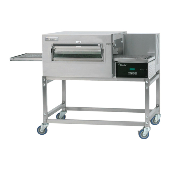
Impinger II Express Series
International Models
MODELS:
Please note that the model numbering system changed
March 2007. The chart below shows the old model
numbering system and its matching new model number
system. Please see Model Number Key section on next
page for additional information.
→
Old Model Number
→
1154-000-EA
→
1154-080-EA
→
1154-V80-EA
→
1155-000-EA
→
1155-080-EA
→
1155-V80-EA
→
1164-000-EA
→
1164-080-EA
P/N: L371086
REV: 5.14.10
Lincoln Foodservice Products, LLC
1111 North Hadley Road
Fort Wayne, Indiana 46804
Telephone: 260.459.8200
Fax: 260.436.0735
Technical Support: 260.459.8200
lincolnfp.com
New Model Number
1154-z00-U-Kxxxx
1154-z00-U-Kxxxx
1157-z00-U-Kxxxx
1155-z00-U-Kxxxx
1155-z00-U-Kxxxx
1158-z00-U-Kxxxx
1164-z00-U-Kxxxx
1164-z00-U-Kxxxx
Advertisement

Subscribe to Our Youtube Channel
Related Manuals for Lincoln Impinger II Express Series


Summary of Contents for Lincoln Impinger II Express Series
- Page 1 PARTS & SERVICE MANUAL Impinger II Express Series International Models MODELS: Please note that the model numbering system changed March 2007. The chart below shows the old model numbering system and its matching new model number system. Please see Model Number Key section on next page for additional information.
-
Page 2: Model Number Key
MODEL NUMBER KEY EXAMPLE: 1154-B00-E-K1801 11 54 - B 00 - E - K1801 Panel Setup Code Agency Code (i.e. CE & RoHS combined) Custom Configuration Code (i.e. General Market Version) Language Code Indicates change to base assembly (i.e. Natural Gas, 230V, 1 phase, 50 Hz) Oven Platform Size (i.e. - Page 3 SEQUENCE OF OPERATIONS IMPINGER II ADVANTAGE DIGITAL EXPRESS SERIES 1154 EXPORT NAT. GAS 230VAC 50 HZ. 1 PHASE SERIES 1155 EXPORT LP GAS 230VAC 50 HZ. 1 PHASE SERIES 1157 EXPORT NAT. GAS 230VAC 50/60HZ 1 PHASE SERIES 1158 EXPORT LP GAS 230VAC 50/60HZ...
- Page 4 SEQUENCE OF OPERATIONS IMPINGER II ADVANTAGE DIGITAL EXPRESS SERIES 1164 EXPORT 400/230VAC 50HZ. 3 PHASE POWER SUPPLY Electrical power to be supplied to the oven by a four conductor service. Brown conductor is hot. Black conductor is hot. Black conductor is hot. Green conductor is ground.
- Page 5 SCHEMATIC DIAGRAM MODEL SERIES 1154, 1155, 1157, 1158 EXPORT EXPRESS SERIES Impinger II – Advantage Digital Express Service Manual - International...
- Page 6 SCHEMATIC DIAGRAM MODEL SERIES 1164 EXPORT EXPRESS SERIES Impinger II – Advantage Digital Express Service Manual - International...
- Page 7 TROUBLESHOOTING GUIDE IMPINGER II ADVANTAGE DIGITAL EXPRESS SERIES 1154 EXPORT NAT. GAS 230VAC 50 HZ. 1 PHASE SERIES 1155 EXPORT LP GAS 230VAC 50 HZ. 1 PHASE SERIES 1157 EXPORT NAT. GAS 230VAC 50/60HZ 1 PHASE SERIES 1158 EXPORT LP GAS 230VAC 50/60HZ 1 PHASE...
- Page 8 2 and Neutral. If voltage is present, proceed with next step, if not, wait 30 seconds, push reset button and try to restart. If this fails, check wires from burner blower motor to the ignition control. If the above checks okay, replace ignition control.
- Page 9 24VAC at transformer secondary. If there is primary voltage, but no secondary voltage, replace control transformer. Conveyor motor Check for supply voltage to the conveyor motor at wire #6 to neutral. If no voltage is present, trace wiring back to the oven fan switch. If voltage is present, but the motor will not run, check the motor windings for opens or shorts.
- Page 10 TROUBLESHOOTING GUIDE IMPINGER II ADVANTAGE DIGITAL EXPRESS SERIES 1164 EXPORT 400/230VAC 50HZ. 3 PHASE REFER TO PROPER SCHEMATIC FOR IDENTIFIED COMPONENTS SYMPTOM POSSIBLE CAUSE EVALUATION Oven fan will not run Incoming power supply Check breaker, reset if required. Check power plug to be sure it is firmly in receptacle.
- Page 11 Oven will not heat Main fan If not operating, refer to “Oven fan will not run”. Control transformer Check for supply voltage to the primary of control transformer. If no voltage is present, trace wiring back to oven fan switch. If voltage is present, check for 24VAC at transformer secondary.
- Page 12 individual elements for opens, shorts and proper resistance. WITH POWER OFF; To check resistance of the elements, remove all leads from the elements and use a digital multimeter. The element resistance should be as follows: 230V – 33 ohm. Replace heating elements as needed. Oven heats with Contactor The contactor has probably failed in the closed position.
- Page 13 replace conveyor motor. If the readings are achieved, proceed. Oven control If the hall effect sensor readings are correct, but there is no speed indicated on the display, replace the oven control Impinger II – Advantage Digital Express Service Manual - International...
- Page 14 REMOVAL, INSTALLATION AND ADJUSTMENTS IMPINGER II ADVANTAGE DIGITAL EXPRESS SERIES CAUTION BEFORE REMOVING OR INSTALLING ANY COMPONENT IN THE IMPINGER OVEN BE SURE TO DISCONNECT ELECTRICAL POWER AND GAS SUPPLY. MAIN FAN – REPLACEMENT A. Shut off power at main breaker. B.
- Page 15 FUSE HOLDER – REPLACEMENT A. Shut off power at main breaker. B. Remove control box cover and front panel. C. Remove wires from fuse holder and mark for reassembly. D. Remove mounting screws or mounting nut on fuse holder and remove fuse holder. E.
- Page 16 TRANSFORMER, CONTROL – REPLACEMENT A. Shut off power at main breaker. B. Remove control panel top and front cover. C. Remove all wires from transformer and mark for reassembly. D. Remove two mounting screws from transformer base and remove transformer. E.
- Page 17 GAS VALVE – REPLACEMENT (S/N 2045408 and Above) A. Shut off power at main breaker. B. Shut off gas supply to the oven and disconnect the flexible gas line to the oven. C. Remove control panel top and front cover. D.
- Page 18 REVERSING SWITCH – REPLACEMENT A. Shut off power at main breaker. B. Remove control panel top and front cover. C. Remove wires from reversing switch and mark for reassembly. D. Remove mounting nut and remove switch. E. Reassemble in reverse order and check system operation. CONVEYOR DRIVE MOTOR –...
- Page 19 S.S. RELAYS – REPLACEMENT A. Shut off power at main breaker. B. Remove control panel top and front cover. C. Disconnect all wires and mark for reassembly. D. Remove screws from mounting bracket and remove contactor. E. Reassemble in reverse order and check system operation. HEATING ELEMENT –...
- Page 20 IMPINGER II ADVANTAGE DIGITAL EXPRESS GENERAL VIEW LETTER PART NUMBER DESCRIPTION 370412 Cross support 370416 Stand side 369231 Caster, 4” w/threaded stem 369232 Adjustable leg 369390 Caster, 4” w/mounting plate Oven door, See “Conveyor / Door” Section 370010 Bottom finger housing 369502 Bottom finger cover 369504...
-
Page 21: General View
GENERAL VIEW Impinger II – Advantage Digital Express Service Manual - International... - Page 22 IMPINGER II ADVANTAGE DIGITAL EXPRESS CONTROL BOX 1154, 1155, 1157, 1158 SERIES LETTER PART NUMBER DESCRIPTION 357067 Hi Limit Switch 369771 Switch Assembly 390129 J-Box Cover 370117 Terminal Block, 5 Pole 370178 Junction Box 9003551 10 Amp Fuse Adapter Assembly 4071234 Beaded Ferrule 369192...
- Page 23 IMPINGER II ADVANTAGE DIGITAL EXPRESS CONTROL BOX 1154 SERIES, 1155 SERIES Impinger II – Advantage Digital Express Service Manual - International...
- Page 24 IMPINGER II ADVANTAGE DIGITAL EXPRESS BURNER ASSEMBLY, NAT. GAS 1154 SERIES, 1157 SERIES LETTER PART NUMBER DESCRIPTION 369556 Nat. Bypass Orifice .061/1.55mm 370401 Ignitor Module, Plug-In 370400 Valve, VK4115 A 1000 369582 Burner Assembly, Nat. Gas Export 370186 Valve, 85294101 369401 Air Shutter Assembly 369589...
- Page 25 IMPINGER II ADVANTAGE DIGITAL EXPRESS BURNER ASSEMBLY Impinger II – Advantage Digital Express Service Manual - International...
- Page 26 IMPINGER II ADVANTAGE DIGITAL EXPRESS CONVEYOR MOTOR ASSEMBY ALL MODELS LETTER PART NUMBER DESCRIPTION 370676 Conveyor Motor 370686 Conveyor Motor Bracket 370671 Coupling Impinger II – Advantage Digital Express Service Manual - International...
- Page 27 IMPINGER II ADVANTAGE DIGITAL EXPRESS CONVEYOR MOTOR ASSEMBY ALL MODELS Impinger II – Advantage Digital Express Service Manual - International...
- Page 28 IMPINGER II ADVANTAGE DIGITAL EXPRESS CONTROL BOX 1164 SERIES LETTER PART NUMBER DESCRIPTION 370672 50 Amp Solid State Relay 370674 Surge Protector 370117 Terminal Block, 5 Pole 390129 J-Box Cover 10002030 Line Filter 369192 Capacitor 9005478 See 1164 Conveyor Motor Assembly Section 370417 Main Control Board 369507...
- Page 29 IMPINGER II ADVANTAGE DIGITAL EXPRESS CONTROL BOX 1164 SERIES Impinger II – Advantage Digital Express Service Manual - International...
- Page 30 OVEN BACK ASSEMBLY ALL MODELS LETTER PART NUMBER DESCRIPTION 369182 369899 Fan shroud 369655 Stand off 370164 Heating Element – 1164 Only 369549 Rear Wall - 1164 369976 Rear Wall – 1154, 1155 369976 Rear Wall – 1157, 1158 369581 Motor mount 369196 Motor –...
- Page 31 OVEN BACK ASSEMBLY ALL MODELS Impinger II – Advantage Digital Express Service Manual - International...
- Page 32 CONVEYOR / DOOR ALL MODELS LETTER PART NUMBER DESCRIPTION 369223 Crumb pan, right and left 369223 Crumb pan, right and left 369666 Conveyor frame assembly 369226 Pan stop 369516 Conveyor bearing 369514 Idler shaft 369515 Sprocket (includes set screw), Regular Conveyor 369978 Set screw 370509...
- Page 33 CONVEYOR / DOOR Impinger II – Advantage Digital Express Service Manual - International...
- Page 34 STAINLESS STEEL ACCESS DOOR ALL MODELS (SN 0908210000875 AND ABOVE) LETTER PART NUMBER DESCRIPTION 369110 Access Door Assembly 371140 Bracket Assembly, Left 371142 Dowel, Access Door 370722 Screw 371143 8-32 x 3/8 Hx Serr Flng 371141 Bracket Assembly, Right 370725 Dowel Thread 371144 Access Door Frame (top or bottom)
- Page 35 ADDENDUM A NEW STYLE OVEN STAND (BEGINNING MARCH 16, 2009) Insert the four Stand Side Bars (G) into the four holes located on each of the Front/Back Assemblies (A). Note: The Stand Side Bar that contains labels should be facing “out” so that the labels can be easily read by the operator. Attach the Stand Side Bars to the Front/Back Assemblies and tighten using the 1 ¾”...
- Page 36 Lincoln Foodservice Products, LLC 1111 North Hadley Road Fort Wayne, Indiana 46804 Telephone: 260.459.8200 Fax: 260.436.0735 Technical Support: 260.459.8200 lincolnfp.com Impinger II – Advantage Digital Express Service Manual - International...
Need help?
Do you have a question about the Impinger II Express Series and is the answer not in the manual?
Questions and answers