Table of Contents
Advertisement
Advertisement
Table of Contents

Related Manuals for Lilin PDR-400


Summary of Contents for Lilin PDR-400
- Page 1 4-CH STANDALONE DVR PDR-400/400IP INSTRUCTION MANUAL...
- Page 2 CAUTION The lightning flash with arrowhead symbol, within an equilateral triangle, is intended to alert the user to the RISK OF ELECTRIC SHOCK presence of uninsulated "dangerous voltage" within the product's enclosure that may be of sufficient magnitude to constitute a risk of electric shock to persons. CAUTION TO REDUCE THE RISK OF ELECTRIC SHOCK, DO NOT OPEN COVER.
-
Page 3: Table Of Contents
CONTENTS 1. Preface Before Installation Specification 2. Illustration 3. System Installation / Setup NTSC / PAL System Selection HDD Installation System Setup a. Camera Select b. Record Select c. Record Mode d. Record Frame Rate e. Video Quality f. Record Schedule g. - Page 4 14. System Operation Monitoring Recording Hard Drive Storage Capacity and Frame Rate Status Data Search and Playback Playback Control Hard Drive Error Auto Detect Manufacturing Default Setting 5. Recording Capacity Reference Chart 6. Remote Viewer (Optional) Preface Internet Browser Connection Diagram Internet Access a.
-
Page 5: Preface
PREFACE Before Installation Thank you for purchasing PDR-400/400IP Stand Alone Digital Video Recorder. We recommend that you read this installation and operation manual throughly before operating your new system. Precautions 1. Avoid installing the equipment in an unstable area. Make sure the area is firm and stable. -
Page 6: Illustration
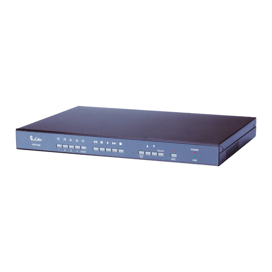
ILLUSTRATION SETUP SELECT POWER PDR-400 QUAD Camera Display Keys / Numeric Keys Function Setup Keys Display First Camera or Number 1 Key. OSD Setup MENU Enter or Escape Key. Display Second Camera or Number 2 Key. Setting Item Select Key. -
Page 7: System Installation/Setup
SYSTEM INSTALLATION/SETUP NTSC / PAL Systems Selection The System can be set up as NTSC or PAL system. System will be set as customer's request before delivery. If necessary, user can switch the system as following steps: 1. Turn off the Power. 2. -
Page 8: System Setup
System Setup Press [MENU/ESC] key to enter OSD setup menu as shown: MAIN MENU CAMERA SELECT 1 2 3 4 RECORD SELECT 1 2 3 4 Press [ ] [ ] keys to select setting item and Press RECORD MODE EACH RECORD FRAME RATE 30 FPS... -
Page 9: Video Quality
5. VIDEO QUALITY (Recording) After entered setup menu, press [ ] [ ] keys to move the arrow sign to "VIDEO QUALITY" and press [SELECT] key to confirm. HIGH = high recording video quality, low compression rate, bigger file size. NORMAL = normal recording video quality, medium compression rate. -
Page 10: Advance Settings
7. Advance Settings After entered setup menu, press [ ] [ ] keys to move the arrow sign to "ADVANCE MENU" and press [SELECT] key to confirm. Monitor displays MAIN MENU ADVANCE MENU CAMERA SELECT 1 2 3 4 PASSWORD CHANGE RECORD SELECT 1 2 3 4 TIME SET... -
Page 11: Keylock
KEYLOCK After entered Advance Menu, press [ ] [ ] keys to move the arrow sign to "KEYLOCK" and press [SELECT] key to confirm. NO = Disable keylock function. YES = Enable keylock function. Factory Default Value : NO Note : Once keylock is enabled, Stop Recording and Clear Hard Drive will be protected by Pressword. -
Page 12: Overwrite Recording (Continuous Recording)
Overwrite Recording (continuous recording) After entered "HARD DRIVE SETUP" menu, press [ ] [ ] keys to move the arrow sign to "OVERWRITE ENABLED" and press [SELECT] key to confirm. YES = when HDD is full, system will overwrite the HDD starting from the beginning. NO = when HDD is full, system will stop recording. -
Page 13: Alarm Record Frame Rate
ALARM RECORD FRAME RATE After entered Alarm Setup menu, press [ ] [ ] keys to move arrow sign to "ALARM RECORD FRAME RATE" and press [SELECT] key to select. There are nine selections for alarm record frame rate : "OFF, 1, 2, 4, 5, 7, 10, 15, 30" FPS. Factory Default Value : 30 Press [MENU/ESC] key to exit when finished or [ ] [ ] keys to select the next setting item. -
Page 14: Auto Record
10. AUTO RECORD After entered setup menu, press [ ] [ ] keys to move arrow sign to "AUTO RECORD" and press [SELECT] key to select auto record time. Monitor displays MAIN MENU 1 2 3 4 CAMERA SELECT 1 2 3 4 RECORD SELECT EACH RECORD MODE... -
Page 15: System Operation
SYSTEM OPERATION When system's power is turned on, system will auto running "Initial HDD". This will last 3 to 5 seconds and showed on monitor screen. Monitoring There are two options for live monitoring : Quad or Each. When quad is selected, monitor screen will show as below EACH Camera numbers System time display... -
Page 16: Recording
Recording When "Camera Select", "Record Select", "Record Mode", "Record Frame Rate", "Video Quality" and "Alarm Setup" are set, [REC] key on the front panel must be pressed and system will start recording according to the setting. When recording is activated, monitor screen will show as below Recording Mode EACH EACH or QUAD... -
Page 17: Data Search And Playback
Data Search and Playback Press [ ] key on panel and screen displays as below: SEARCH TIME HDD to be searched HARDDRIVE : MASTER Search Time Entered 03/11/21 10:54:10 03/11/21 10:59:01 The latest data in HDD 01 TIME 2003/11/21 10:54:10 STOP Recording status 02 TIME 2003/11/21 10:54:10... -
Page 18: Playback Control
Playback Control Under playback, following keys can be operated 1. [ ] Fast Forward (1x, 2x, 3x, 4x) 2. [ ] Fast Rewind (3x) 3. [ ] Press once to pause when playing, press again for frame by frame play. ] Press once to pause when playing, press again for frame by frame play. -
Page 19: Recording Capacity Reference Chart
RECORDING CAPACITY 80GB HARD DRIVE NTSC Video Signal Recording Full screen QUAD screen Format Recording High Normal Medium Basic High Normal Medium Basic Quality 1893 / 40 1463 / 52 1263 / 60 1127 / 68 2444 / 31 1741 / 44 1587 / 48 1389 / 55 30 fps... -
Page 20: Remote Viewer (Optional)
REMOTE VIEWER (OPTIONAL) PREFACE PDR-400IP supports the flexibilities for multi-users accessing live monitoring and retrieving stored video remotely for the DVR via Internet Browser. No software application installation is required. PDR-400IP provides excellent video quality in remote monitoring and is capable of viewing different video size for different network bandwidth considerations. -
Page 21: Connection Diagram
CONNECTION DIAGRAM 1. Internet Camera 1 Camera 2 Camera 3 Camera 4 RJ-45 (Crossover) Brown Brown White/Brown White/Brown Monitor Green Orang White/Bule Whiet/Blue Blue Blue White/Green White/Orange Orange Green White/Orange White/Green Video Out PDR- 400 QUAD RJ-45 (Crossover) Camera 1 Camera 2 Camera 3 Camera 4... -
Page 22: Internet Access
Internet Access Before using PDR-400IP for Internet access, please make sure that the following network configurations get setup properly : 1. Networking Setting Network IP address, subnet mask, and gateway are setup correctly. Always, consult your network administrator before installing PDR-400IP. Use IPScan software tool (shipped within the product CD) to search PDR-400IP, if PDR-400IP is accessible in your local network. -
Page 23: Ip Address Configuration
3. IP Address Configuration There are basically three ways for setup IP address of PDR-400IP. A user can determine which way is the easiest way if the software or hardware is available at the installation site. Please follow one of the following ways to setup IP address. Use front keypad of PDR-400IP to change IP address, if a monitor is properly setup. -
Page 24: Menu Systems
5. Menu Systems To use PDR-400IP's menu systems, please right click on video box (ActiveX control). A menu with three menu items gets pop up. A user can adjust video property, perform video record, and zoom the video source. Door 30 FPS 30 FPS 38358MB... - Page 25 Recording To record PC AVI file, please click on Recording menu item. An AVI Capturing dialog box shows up. A user can specify the AVI recording path in the Save As edit box. Click on Start button. Live video or stored video (playback) can be captured and saved into local PC. Click on Stop button to stop the recording operation.
-
Page 26: Network Features
Network Features After login PDR-400IP as administrator, there are two main features-system operation and configuration. Operation and configuration features are described as follows : 1. PDR-400IP Operational HTML Page PDR-400IP operational HTML page layout: Door 30FPS 30FPS 48752MB 48752MB EACH 2005 / 01 / 08 04:43:15 2005 / 01 / 08 04:43:15 <+>... -
Page 27: Configuration
Text Stamp Text stamp feature allows a user to add text description for the video ActiveX. To setup text stamp, please see "Video Setting Text Stamp" for detail. Video ActiveX Control Video ActiveX control is a software component displaying video streaming embedded inside an HTML page. -
Page 28: Server Setting
Server Setting Server settings contain PDR-400IP server's system information such as MAC address, firmware version, users, system clock, and other system commands. To change or use the information, please follow the instructions in this chapter. General Settings MAC address MAC address stands for Media Access Control. In short, MAC address can represent unique identification for IP-based products. -
Page 29: Network
Timer PDR-400IP allows a user to change system timer via standard HTML web page. To change PDR-400IP's system timer, please enter the date and time in the edit boxes. Click on Submit button to apply this operation. Note : Change system timer may ruin the recorded video, since the time for recorded video is different from system timer. -
Page 30: Video Setting
DHCP Setting Router, gateway, or other software DHCP server can dynamically distribute an IP address to PDR-400IP. A user can use IPScan utility to launch Internet browser for PDR-400IP's video. To enable DHCP, click on Enable radio button and click on Submit button. Note : Once the DHCP gets enable, PDR-400IP uses IP address from DHCP server instead of the IP address assigned by IP Settings. -
Page 31: Backup Still Image
Video Quality There are three video quality levels that a user can set for PDR-400IP. Basically, better video quality setting a user can get better video image. However, if the bandwidth is a concern, please lower the video quality setting. 3. -
Page 32: Appendix
APPENDIX IPScan Software IPScan utilizes ARP protocol for scanning all PDR-400IP within a LAN environment. To perform IPScan utility, please follow the instruction below : Execute IPScan.exe on product CD. Click on Refresh button. IPScan scans all the IP devices and shows all PDR-400IP devices in the device list box. -
Page 33: Ping Utility
Ping Utility One can also use ping utility for detecting an IP device. Please follow the instructions below : Execute ping utility. Click on Start Execute. Type "command" in the command line box. A command window shows up. Type "ping 192.168.0.90". 192.168.0.90 is the default IP address. If the device is not properly set, ping utility shows Request Time out. - Page 34 MERIT LILIN ENT. CO., LTD http://www.meritlilin.com 66-400CSE...
Need help?
Do you have a question about the PDR-400 and is the answer not in the manual?
Questions and answers