Table of Contents
Advertisement
Advertisement
Table of Contents

Related Manuals for TPI 270


Summary of Contents for TPI 270
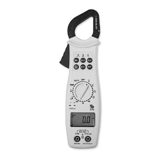
- Page 1 Digital Clamp-on Meter Instruction Manual...
-
Page 2: Table Of Contents
TABLE OF CONTENTS A. INTRODUCTION 1. Congratulations ......3 2. Product Description ....3 Declaration of Conformity ..4 B. SAFETY CONSIDERATIONS ....5 C. TECHNICAL DATA Features and Benefits....6 2. Product Applications ....7 3. Specifications......8 D. MEASUREMENT TECHNIQUES Controls and Functions ....12 Step by Step Procedures: ..14 E. -
Page 3: Introduction
A. INTRODUCTION 1. Congratulations!! Thank you for purchasing TPI products. The 270 is easy to use and is built to last. It is backed by a 3 year limit- ed warranty. Please remember to complete and return your product warranty registration card. -
Page 4: Ec Declaration Of Conformity
3. EC Declaration of Conformity This is to certify that TPI Model 270 conforms to the protection requirements of the council directive 89/336/EEC, in the approximation of laws of the member states relating to Electromagnetic compatibility and 73/23/EEC. The Low Voltage Directive by application of... -
Page 5: Safety Considerations
GENERAL GUIDELINES ALWAYS • Test the 270 before using it to make sure it is operating properly. • Inspect the test leads before using to make sure there are no breaks or shorts. -
Page 6: Technical Data
INTERNATIONAL SYMBOLS CAUTION: RISK OF ELECTRIC SHOCK AC (Alternation Current) DC (Direct Current) REFER TO INSTRUCTION MANUAL GROUND DOUBLE INSULATION EITHER DC OR AC C. TECHNICAL DATA 1. Features and Benefits Agency Meets CE and IEC 1010. Analog Bar Displays rapidly changing input Graph signals. -
Page 7: Product Applications
2. Product Applications Perform the following tests and/or measurements with the 270 and the appropriate function: HVAC/R DCmV • Thermocouples in furnaces. • Heat anticipator current in thermostats. • Line voltage. ACV or DCV • Control circuit voltage. DC m A •... -
Page 8: Specifications
3. Specifications IEC 1010 Over Voltage: CAT II - 1000V CAT III - 600V UL 3111 Pending Pollution Degree 2 Temperature for gauranteed accuracy: 23ºC +5ºC DC VOLTS Range Res. Accuracy 400mV 0.1mV Impedance: 0.001V +/-(0.5% of reading + 2 digits) 10MW 0.01V Overload Protection:... - Page 9 DC Microamps Range Res. Accuracy 40uA 0.01mA +/-(0.8% of reading + 2 digits) Overload Protection: 400uA 0.1mA 0.5A / 600V Fuse *DC microamps are measured with the test leads in series with the circuit under test. OHM ( Resistance, Range Res.
-
Page 10: Diode Test
+ (1%+2ºF) -3ºF to 749ºF + (2%+1.5ºF) 750ºF to 1000ºF + (2%+4ºF) -40ºF to -4ºF Overload Protection: 60VDC or 30VAC RMS **Celsius version of the 270 is available Warning: Use only correct type and overvoltage category rated test leads. Remove the temperature probe when using the test leads or amp clamp. - Page 11 Capacitance Range Res. Accuracy 0.001nF ±(1% of reading +2 digits) 40nF 0.01nF 400nF 0.1nF Overload Protection: 0.001mF 500VDC or AC RMS 40mF 0.01mF 400mF 0.1uF 0.001mF 40mF 0.01mF ±(3% of reading +5 digits) nF= nanofarad, mF= microfarad, mF= millifarad General Max Voltage between any 600V input and ground Fuse Protection ( m m A range) 0.5A/600V...
-
Page 12: Measurement Techniques
D. MEASUREMENT TECHNIQUES 1. Controls and Functions: Push Buttons Activates Relative mode. Press and hold for 2 seconds to deacti- vate. Holds the reading on the display until the button is pushed a second time. Activates manual ranging. Press and hold for 2 seconds to return to auto ranging. - Page 13 1. Controls and Functions: (cont.) Rotary Switch Turns the 270 completely off. Used to measure DC volts. Used to measure AC volts. Used to measure resistance. Used to measure continuity. Selects diode test function. Selects capacitance test function. Selects frequency test function.
-
Page 14: Step By Step Procedures
4. Set rotary switch to the V range. 5. Connect test leads to circuit to be measured. 6. Reconnect power to circuit to be measured. 7. Read the voltage on the 270. Optional Modes (See Other Features Section) •... -
Page 15: Measuring Ac Voltage
4. Set rotary switch to the V range. 5. Connect test leads to circuit to be measured. 6. Reconnect power to circuit to be measured. 7. Read the voltage on the 270. Optional Modes (See Other Features Section) •... -
Page 16: Measuring Resistance
3. Plug red test lead into V/ input jack. 4. Set the rotary switch to the function. 5. Connect test leads to circuit to be measured. 6. Read the resistance value on the 270. Optional Modes (See Other Features Section) • D-H:... - Page 17 Measuring AC Amperage CAUTION! Do not attempt to make a current measurement with the test leads. The 270 measures the current by clamping the jaw around one conductor (wire). Clamping around more than one wire will result in erroneous readings. Make sure the temperature probe is NOT plugged in during this test.
-
Page 18: Measuring Continuity
3. Plug red test lead into V/ input jack. 4. Set the rotary switch to the position. 5. Connect test leads to circuit to be measured. 6. The 270 will beep and the LED will illuminate at resistances of 35 or lower. Optional Modes (See Other Features Section) •... - Page 19 Measuring Diodes WARNING! Do not attempt to make diode measurements with the circuit energized. For accurate tests, remove the diode completely from the circuit prior to measuring it. Make sure the tempera- ture probe is NOT plugged in during this test. Instrument set-up: FUNC.
-
Page 20: Measuring Capacitance
Measuring Capacitance WARNING! All capacitance measurements are to be made on de-energized circuits with all capacitors discharged only. Failure to de-energize and discharge capacitors prior to measuring them could result in instrument damage and/or personal injury. Make sure the temper- ature probe is NOT plugged in during this test. -
Page 21: Measuring Frequency
Measuring Frequency WARNING! Never attempt a frequency measurement with a voltage source greater than 500V. Determine the voltage of any unknown fre- quency source before connecting the instrument in frequency mode. Make sure the temperature probe is NOT plugged in during this test. - Page 22 A Connect the test leads in series to the circuit to be measured. Reconnect power to circuit to be measured. Read the current on the 270. Optional Modes (See Other Features Section) • D-H: Freezes the reading on the LCD.
-
Page 23: Measuring Temperature
Measuring Temperature CAUTION! Do not attempt to make a temperature measurement with the test leads connected to the 270. Remove the test leads and insert the K-type temperature probe. Instrument set-up: FUNC. BLACK MINIMUM MAXIMUM TEST LEAD TEST LEAD READING READING 400ºF... -
Page 24: Other Features
3. Put the arrow marked on the jaw close to the wire under test. 4. If voltage is present the 270 will beep and the NCV LED will illuminate. 5. If voltage is not detected, confirm the result by perform- ing a voltage measurement as outlined earlier in this manual. - Page 25 To clear or exit relative mode, press and hold the REL button for approximately two seconds and the 270 will beep and return to normal operation. Note: Differential temperature measurements can be made using relative mode. See the application note...
- Page 26 MIN and the minimum reading recorded. Press the MAX/MIN button again and MAX MIN will blink and the 270 will display the measured value in real time. Steps 2 and 3 can be repeated to read the maximum and minimum recorded values.
- Page 27 NOTE: Peak mode can display up to 70 counts on the dis- play when first activated. For example, if the 270 is set to the ACA function and manually ranged to the 40A range, when P-H is activated the display can read up to 0.70.
- Page 28 LCD display. This function is useful when measuring in locations where the display is difficult to read. LED Indicators The 270 is equipped with three LED indicators at the top near the jaw. HI-V This indicator flashes and the 270 beeps when the test leads are in contact with a voltage of 30V AC/DC or more.
-
Page 29: Application Notes
F. Application Notes (AC Volts) Disconnect power from the terminal block, find the fuse or circuit breaker that con- trols the block and turn it off. Set up the meter following the steps under “Measurement Procedure” on page 15. Then proceed with the following: •Connect the red test lead to the hot side of the block and... - Page 30 Application Notes (DC Volts) The 270 will accurately measure rectified DC Voltages like those encountered in furnaces and other appliances even though many of these devices do not have output filtering or other signal conditioning. When measuring DC Voltage of a bat-...
- Page 31 Application Notes (Resistance) When measuring resistance of a motor, make sure the power is disconnected prior to testing. Set up meter following steps under “Measurement Procedure” on page 16, and proceed with the following: • Connect the red test lead to one power input line of the motor and the black test lead to the other power input line of the motor.
- Page 32 Application Notes (AC Amps) When measuring AC Amps of a motor there are two types of measurements that can be made, running current and in-rush or start-up current. Start-up current will usually be much higher than running current. Set up the meter following the steps under “Measurement Procedure”...
- Page 33 • Remove the test leads from the input jacks. Insert the K-type thermocouple probe into the input jack on the 270. Set the 270 to the desired TEMP function. • Touch the temperature probe sensor to the device under test (T1).
-
Page 34: Trouble Shooting Guide
G. Trouble Shooting Problem Probable Causes Does not power up • Dead or defective battery • Broken wire from battery snap to PCB Won’t display DC • Open fuse microamp readings • Open test lead • Improperly connected to circuit under test All functions except •... -
Page 35: Maintenance
Disconnect and remove all test leads from live circuits and from the 270. b. Loosen the screw from the back of the 270 battery / fuse cover. c. Remove the battery / fuse compartment cover. -
Page 36: Accessories
Accessories Standard Accessories Part Number 9 Volt Alkaline Battery A009A Test Lead Set (1000V CATIII 10A) A085 0.5A / 600V Fuse A107 Soft Carrying Pouch A270 Optional Accessories Part Number Fused Test Lead Kit FTLK3 Deluxe Test Lead Set TLS2000RB Carbon Monoxide Adapter A771 Pressure Adapter... - Page 40 270 SPECIFICATIONS (PARTIAL LIST) ±0.5% Basic DCV Accuracy (also see pages 8-11) Func. Range Res. 400mV 0.1mV 0.001V 0.01V 400V 0.1V 600V 400mV 0.1mV 0.001V 0.01V 400V 0.1V 750V 0.1A 400A 400W 0.1W 0.001kW 40kW 0.01kW 400kW 0.1kW 0.001MW 40MW 0.01MW...
Need help?
Do you have a question about the 270 and is the answer not in the manual?
Questions and answers