
Related Manuals for TPI 133


Summary of Contents for TPI 133
-
Page 1: Digital Multimeter
Digital Multimeter Instruction Manual GlobalTestSupply www. .com ducts Online at: sales@Global... -
Page 2: Table Of Contents
TABLE OF CONTENTS page A. INTRODUCTION 1. Congratulations ....3 2. Product Description ....3 3. -
Page 3: Introduction
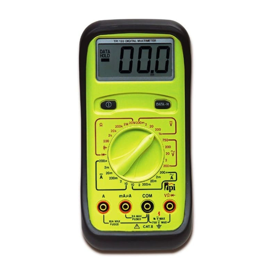
Please remember to complete and return your product warranty registration card. 2. Product Description The 133 is a hand held manual ranging DMM. It features extra large numerals on the LCD, and Data Hold for all functions and ranges. The 133 is an affordable choice offering measurements in all of the basic electrical functions. -
Page 4: Ec Declaration Of Conformity
3. EC Declaration of Conformity This is to certify that model 133 conforms to the protection requirements of the council directive 89/336/EEC, in the approximation of laws of the member states relating to Electromagnetic compatibility and 73/23/EEC, The Low Voltage Directive by application of the following standards:... -
Page 5: Safety Considerations
GENERAL GUIDELINES ALWAYS • Test the 133 before using it to make sure it is operating properly. • Inspect the test leads before using to make sure there are no breaks or shorts. -
Page 6: Technical Data
INTERNATIONAL SYMBOLS CAUTION: RISK OF ELECTRIC SHOCK AC (ALTERNATING CURRENT) DC (DIRECT CURRENT) REFER TO INSTRUCTION MANUAL GROUND FUSE DOUBLE INSULATION ON/OFF, PUSH BUTTON SWITCH C. TECHNICAL DATA 1. Features and Benefits Safety Meets CE and IEC 1010 requirements. UL Listed to U.S. and Canadian Safety Standards. -
Page 7: Product Applications
2. Product Applications Perform the following tests and/or measurements with the TPI 133 and the appropriate function: HVAC/R FUNCTION DCmV • Thermocouples in furnaces or gas applications. • Heat anticipator current in thermostats. • Line voltage. ACV or DCV • Control circuit voltage. -
Page 8: Specifications
3. Specifications IEC 1010 Over Voltage: CAT II - 1000V CAT III - 600V UL 3111-1 Pollution Degree 2 a. DCV Range Resolution Accuracy Impedance 200mV 0.1mV ±0.5% of reading, 0.001V ±2 digits 0.01V 200V 0.1V 1000V b. ACV (45Hz to 450Hz) Range Resolution Accuracy... - Page 9 d. ACA Range Resolution Accuracy Overload Protection 200µA 0.1µA ±1% of reading, Fuse* 0.001mA ±3 digits F600V, 2A, 31CM 20mA 0.01mA 200mA 0.1mA ±1.8% of reading, 0.001A ±3 digits 0.01A ± 3% of reading, ± 7 digits Fuse* F600V, 10A, 31CM e.
-
Page 10: Measurement Techniques
D. MEASUREMENT TECHNIQUES 1. Controls and Functions: Push Buttons Turns the 133 on and off. Data-H Activates the Data Hold function. Rotary Switch Used for measurement of DC Volts. Select the best range for the voltage to be measured. Used for measurement of AC Volts. Select the best range for the voltage to be measured. -
Page 11: Step By Step Procedures
Plug black test lead into the COM input jack. Plug red test lead into V input jack. Set the rotary switch on the 133 to the desired range in the DCV function depending on the voltage to be measured. Connect test leads to circuit to be measured. -
Page 12: B) Measuring Ac Volts
b. Measuring AC Volts CAUTION! Do not attempt to make a voltage measurement if a test lead is plugged in the A or µmA input jack. Instrument damage and/or personal injury may result. WARNING! Do not attempt to make a voltage measurement of more than 1000V or of a voltage level that is unknown. -
Page 13: C) Measuring Dc Amps
2. Plug black test lead into COM input jack. 3. Plug red test lead into V input jack. 4. Set the rotary switch on the 133 to the desired range in the ACV function depending on the voltage to be measured. - Page 14 Plug red test lead into mAµA or A input jack depending on value of current to be measured. Set the rotary switch on the 133 to the desired range in the DCA function depending on the current to be measured and the input jack the red test lead is inserted into.
-
Page 15: D) Measuring Ac Amps
Plug red test lead into mAµA or A input jack depending on value of current to be measured. Set the rotary switch on the 133 to the desired range in the ACA function depending on the current to be measured and the input jack the red test lead is inserted into. - Page 16 Application Notes When measuring resistance of a motor, make sure the power is disconnected prior to testing. Set up the meter following steps under “Measurement Procedure” on page 17, and then proceed with the following: • Connect the red test lead to one power input line of the motor and the black test lead to the other power input line of the motor.
-
Page 17: E) Measuring Resistance
Plug black test lead into the COM input jack. Plug red test lead into the V input jack. Set the rotary switch on the 133 to the desired range in the OHM function depending on the voltage to be measured. -
Page 18: Measuring Diodes
Plug the black test lead into the COM input jack. Plug the red test lead into the V input jack. Set the rotary switch on the 133 to the position. Connect the black test lead to the banded end of the diode and the red test lead to the non-banded end of the diode. -
Page 19: G) Continuity Buzzer
Plug the black test lead into the COM input jack. Plug the red test lead into the V input jack. Set the rotary switch on the 133 to the position. Connect the test leads to the circuit to be measured. -
Page 20: Accessories
Part No. 9V Battery A009 Fuse, 2 Amp A102 Fuse, 10 Amp A110 Test Lead Set A040 Rubber Boot (133 only) A101 Optional Accessories Part No. Deluxe Test Lead Set SDK1C IEC 1010 Deluxe Test Lead Kit TLS2000BC Temperature Adapter... -
Page 21: Maintenance
Remove old battery and replace it with new battery. Reassemble instrument in reverse order from above. Fuse Replacement: Both of the 133 “A” and “mAµA input jacks are fuse protected. Use only Fast Blow, 600 Volt fuses with correct current ratings. Failure to do so will void all warranties. -
Page 22: Trouble Shooting Guide
G. TROUBLE SHOOTING GUIDE Problem Probable Causes Does not power up • Dead or defective battery • Broken wire from battery snap to PCB Won’t display current readings • Open fuse • Open test lead • Improperly connected to circuit under test All functions except ohms read high •... - Page 23 WARRANTY Please refer to product warranty card for warranty statement. GlobalTestSupply www. .com ducts Online at: sales@Global...
- Page 24 ±0.5% Basic DCV Accuracy (also see pages 9-11) Function Range Resolution 200mV 0.1mV 0.001V 0.1V 200V 0.1V 1000V 200mV 0.1mV 0.001V 0.01V 200V 0.1V 750V 200µA 0.1µA 0.001mA 20mA 0.01mA 200mA 0.1mA 0.001A 0.01A 200µA 0.1µA 0.001mA 20mA 0.01mA 200mA 0.1mA 0.001A 0.01A...
Need help?
Do you have a question about the 133 and is the answer not in the manual?
Questions and answers