
Related Manuals for TPI 183A


Summary of Contents for TPI 183A
- Page 1 183A Digital Multimeter (DMM) Confidential & proprietary information of Snap-on. Do not reproduce.
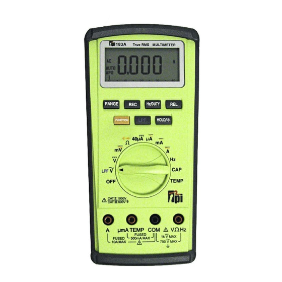
- Page 2 Digital Multimeter Sections Four Basic Sections of the Multimeter 1. Digital Display 2. Push Button Functions 3. Rotary Dial Selector 4. Test Lead Terminals Confidential & proprietary information of Snap-on. Do not reproduce.
- Page 3 Digital Multimeter Sections • Digital Display Readings and Locations on Start-up Button Low Battery symbol Dial Setting Icon Functions Area will appear only when Reference Area power is low Voltage Type AC or DC Auto Ranging on Start-up Auto Power Off Display of the Measured Value Analog Bar Graph...
- Page 4 Digital Multimeter Sections • DMM Push-Buttons Enhance Dial Functions Hz/DUTY toggles activates activates recording of between Frequency Relative Mode MIN (minimum) and (Hertz - Hz) or Duty - sets display to MAX (maximum) Cycle (%) on AC-Volts, zero values AC-Amps, or Hz - factors out RANGE undesired...
- Page 5 Digital Multimeter Sections • DMM Push-Buttons Enhance Dial Functions HOLD freezes a value on the display - a second press removes the hold going back to a live value – activates toggles between FUNCTION backlight Continuity Buzzer and Diode test on the Ohm setting LPF (Low Pass...
- Page 6 Digital Multimeter Sections • DMM Rotary Dial Symbol Definitions Ohms (or resistance) 40 micro amps DC max. toggle to Continuity current setting-measures or Diode Test tiny current draw in DC AC or DC selectable 4000 micro millivolts amps max. current setting Volts selectable AC or DC for very low...
- Page 7 Digital Multimeter Sections • DMM Rotary Dial Symbol Definitions 400 milli Amp max. current setting selectable AC or DC for low current draw 10 Amp max current setting selectable AC or DC HERTZ frequency measurements CAPACITANCE measures capacitors TEMP (TEMPERATURE) measures degrees C &...
- Page 8 Digital Multimeter Sections • DMM - Test Lead Terminal Symbols Volts/OHMS/Hertz TEMP, Micro & COMMON red lead milliamps black lead connection connection red lead connection used for most used for Voltage, 500 milliamp (½ measurements Ohms(resistance) amp) fused terminal (Typically Ground) Diode Test, Continuity, Hertz Amps...
-
Page 9: Button Functions
BUTTON FUNCTIONS Confidential & proprietary information of Snap-on. Do not reproduce. - Page 10 Digital Multimeter – RANGE Button Use with the following Rotary Dial settings Converts meter from Auto-Ranging to Manual-Ranging 1. Press button once for manual range mode 2. Press again to move decimal 3. Hold down button for 3 seconds to go back to Auto-ranging Confidential &...
- Page 11 Digital Multimeter – Record Button Use with the following Rotary Dial settings Records MAXIMUM and MINIMUM READINGS 1. Press button to activate record (MAX) 2. Press again to toggle to MIN or MAX 3. Hold button for 3 seconds to exit the Record function Confidential &...
- Page 12 Digital Multimeter – Hz/Duty Button Use with the following Rotary Dial setting Changes from Hertz to Duty Cycle 1. Press Hz/DUTY button to toggle between Hertz & Duty Cycle (%) Confidential & proprietary information of Snap-on. Do not reproduce.
- Page 13 Digital Multimeter – Relative Button Relative (REL) Function: Factors Out Lead Resistance on Sensitive Readings Zero’s the display 1. Press REL button to activate Zero display 2. Press again to deactivate Confidential & proprietary information of Snap-on. Do not reproduce.
- Page 14 Digital Multimeter – Function Button Use with the following Rotary Dial setting Function: Adds additional functions (DC to AC voltage, Continuity and Diode) to orange marked dial settings Toggles TEMP F to C 1. Press FUNCTION button to toggle to additional functions Confidential &...
- Page 15 Digital Multimeter – LPF Button Use with the following Rotary Dial setting Changes from live AC Volts to Averaged AC volts to slow a jumpy reading 1. Press LPF (Low Pass Filter) to activate averaging filter 2. Press again to deactivate the LPF Confidential &...
- Page 16 Digital Multimeter – Hold Button Use with the following Rotary Dial setting Holds a desired reading or activates the backlight 1. Press Hold/* button to capture a reading 2. Press again to deactivate Activates Backlight button held down for 3 seconds Press and hold to Confidential &...
- Page 17 Confidential & proprietary information of Snap-on. Do not reproduce.
- Page 18 Digital Multimeter Amperage Testing • NEVER exceed the maximum amperage of the meter terminal (either 500mA or 10 amps) • Always start with the Amps setting first to verify if the milliamps or microamps can be used safely • ***REMOVE THE RED TEST LEAD IMMEDIATELY from the meter when done performing any amperage test*** •...
- Page 19 Digital Multimeter Amperage Testing • The meter MUST be connected in SERIES when preforming amperage tests • This requires a break in the circuit which the meter can then be connected into, which recompletes the circuit through the meter with test leads Confidential &...
- Page 20 Digital Multimeter Amperage Testing • The meter MUST be connected in SERIES when preforming amperage tests • Do NOT connect it in parallel as you would for a voltage test. THE FUSE WILL BLOW Parallel = Voltage Test Series = Amperage Test Confidential &...
- Page 21 FUSES Confidential & proprietary information of Snap-on. Do not reproduce.
- Page 22 Digital Multimeter Enhancements • Always Test for Good Fuses Before Using a Meter 1. Put the red lead terminal into the VΩHz terminal – no black lead needed. 2. Remove the red lead alligator clip 3. Move the Rotary Dial to Ω (Ohms).
- Page 23 Digital Multimeter Enhancements • Always Test for Good Fuses Before Using a Meter 5. Touch the red probe to metal µmA TEMP inside the terminal – Any numeric value including 0.000 indicates a good fuse – Any non-numeric value including OL indicates a bad fuse Confidential &...
- Page 24 Digital Multimeter Enhancements • Always Test for Good Fuses Before Using a Meter 6. Touch the red probe to metal inside the terminal – Any numeric value including 0.000 indicates a good fuse – Any non-numeric value including OL indicates a bad fuse Confidential &...
- Page 25 Digital Multimeter Enhancements • If a Bad Fuse is Detected 1. Remove the Protective Boot 2. Turn the Meter with Back Facing Up 3. Unscrew 3 Lower Screws 4. Remove the Protective Cover 5. Locate Bad Fuse • 10A • 0.5A 6.
- Page 26 Digital Multimeter Enhancements • Fuse Protection – There IS a Difference • Fuses are designed specifically for multimeters Lower CAT • Prevent arcing at fuse holder rating fuses Exact replacements are critical to maintain the safety (category) rating • Improper fuse replacement can be deadly Confidential &...
- Page 27 Digital Multimeter Enhancements • Fuses: There IS a difference!! • Ceramic fast blow fuses have a much higher "breaking capacity” or the fuse’s ability to interrupt current flow without being destroyed or arced over Confidential & proprietary information of Snap-on. Do not reproduce.
- Page 28 TEST LEADS Confidential & proprietary information of Snap-on. Do not reproduce.
- Page 29 Digital Multimeter Enhancements • Always Check for Good Test Leads Before Using a Meter 1. Insert red lead into VΩHz terminal 2. Insert black lead into COM terminal 3. Rotate the Dial setting to Ω (Ohms) Confidential & proprietary information of Snap-on.
- Page 30 Digital Multimeter Enhancements • Always Check for Good Test Leads Before Using a Meter 3. Quality test leads will be double insulated (both an inner and outer insulation barrier) to better protect the user 4. The inner insulation layer is white, so it is easy to spot any cuts or other damage against the red and black...
- Page 31 Digital Multimeter Enhancements • Always Check for Good Test Leads Before Using a Meter 4. Press the Function button until the: is visible on the display 5. Use the alligator clips. Clip red & black leads together 6. Audible signal means leads should be good 7.
- Page 32 End of the 183A METER Introduction Confidential & proprietary information of TPI. Confidential & proprietary information of Do not reproduce. Snap-on. Do not reproduce.
Need help?
Do you have a question about the 183A and is the answer not in the manual?
Questions and answers