Table of Contents
Advertisement
Quick Links
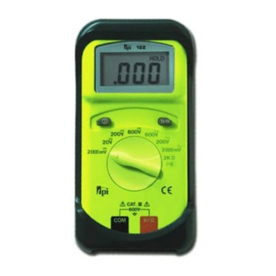
Digital Multimeter 122
Instruction Manual
Test Products International, Inc.
9615 SW Allen Blvd., Ste. 104
Beaverton, OR USA 97005
503-520-9197 • Fax: 503-520-1225
tpiusa@msn.com
Test Products International, Ltd.
342 Bronte Road South, Unit 9
Milton, Ontario L9T5B7
Canada
905-693-8558 • Fax: 905-693-0888
L122M • 12/1/97 copyright © 1998 Test Products International, Inc.
Advertisement
Table of Contents

Related Manuals for TPI 122


Summary of Contents for TPI 122
- Page 1 Digital Multimeter 122 Instruction Manual Test Products International, Inc. 9615 SW Allen Blvd., Ste. 104 Beaverton, OR USA 97005 503-520-9197 • Fax: 503-520-1225 tpiusa@msn.com Test Products International, Ltd. 342 Bronte Road South, Unit 9 Milton, Ontario L9T5B7 Canada 905-693-8558 • Fax: 905-693-0888...
-
Page 2: Ec Declaration Of Conformity
EC DECLARATION OF CONFORMITY This is to certify that model 122 conforms to the protection requirements of the council directive 89/336/EEC, in the approximation of laws of the member states relating to Electromagnetic compatibility and 73/23/EEC, The Low Voltage Directive by application of the following standards:... -
Page 3: Safety Considerations
Have someone check on you periodically if working alone. • Have a complete understanding of circuit being measured. • Disconnect power to circuit, then connect test leads to the 122, then to cir- cuit being measured. NEVER • Attempt to measure unknown high voltages. -
Page 4: International Symbols
Easy to read at all angles and the majority of lighting levels. Data Hold Freeze readings on the display. Rubber Boot Added protection when the instrument is dropped. (122NB does not include boot.) Versatile Use accessories like a carbon monoxide attachment to expand the capabilities of the 122. -
Page 5: Product Applications
PRODUCT APPLICATIONS Perform the following with the TPI 122 and appropriate function: HVAC/R FUNCTION • Line voltage. ACV or DCV • Control circuit voltage. OHMS • Heating element resistance (continuity). OHMS • Compressor winding resistance. OHMS • Contactor and relay coil resistance. - Page 6 SPECIFICATIONS (cont.) IEC 1010 Over Voltage: CAT II - 1000V, CAT III - 600V Pollution Degree 2 b. DCV Range Resolution Accuracy Impedance 2000mv ±0.5% of reading, 10M Ohm 0.01V ±2 digits 200V 0.1V 600V 0.1V c. ACV (45Hz to 450Hz) Range Resolution Accuracy...
-
Page 7: Measurement Techniques
MEASUREMENT TECHNIQUES 1. Controls and Functions: Push Buttons Turns the 122 on and off. Activates the Data Hold function. Rotary Switch Used for measurement of DC Volts. Select best range for the voltage to be measured. Used for measurement of AC Volts. Select best range for the voltage to be measured. -
Page 8: A.measuring Dc Volts
Plug the black test lead into the COM input jack. Plug red test lead into V/ Ω Ω input jack. Set rotary switch on 122 to desired range in DCV function depending on the voltage to be measured. Connect the test leads to the circuit to be measured. -
Page 9: Measuring Ac Volts
2. Plug the black test lead into the COM input jack. 3. Plug red test lead into V/ Ω Ω input jack. 4. Set rotary switch on the 122 to desired range in ACV function depending on the voltage to be measured. -
Page 10: Measuring Resistance
Plug the black test lead into the COM input jack. Plug the red test lead into the V/ Ω Ω input jack. Set rotary switch on the 122 to 2k Ω Ω function depending on the voltage to be measured. -
Page 11: Continuity Buzzer
Plug the black test lead into the COM input jack. Plug the red test lead into the V/ Ω Ω input jack. Set the rotary switch on the 122 to the position. Connect the test leads to the circuit to be measured. -
Page 12: Standard Accessories
Carefully pull apart front and rear instrument housing. Remove old battery and replace it with new battery. Reassemble instrument in reverse order from above. Cleaning your 122 Use a mild detergent and slightly damp cloth to clean the surfaces of 122.
Need help?
Do you have a question about the 122 and is the answer not in the manual?
Questions and answers