Table of Contents
Advertisement
Quick Links
Advertisement
Table of Contents

Related Manuals for TPI 183A


Summary of Contents for TPI 183A
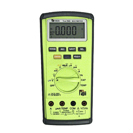
- Page 1 183A Digital Multimeter Instruction Manual...
-
Page 2: Table Of Contents
Congratulations ....3 Thank you for purchasing TPI products. The meter is easy Product Description ....3 to use and is built to last. -
Page 3: Ec Declaration Of Conformity
Sources such as hand held • Test the 183A before using it to make sure it is radio transceivers, radio and TV transmitters, operating properly. vehicle radios and cellular phones generate •... -
Page 4: Technical Data
INTERNATIONAL SYMBOLS 2. Product Applications Perform the following tests and/or measurements DANGEROUS VOLTAGE with the TPI 183A and the appropriate function: AC (ALTERNATING CURRENT) HVAC/R DC (DIRECT CURRENT) FUNCTION DCmV • Thermocouples in furnaces or gas REFER TO INSTRUCTION MANUAL applications. -
Page 5: Specifications
3. Specifications f. ACV (True-RMS, 1kHz - 20kHz) IEC 61010-1 Over Voltage: Range Resolution Accuracy Impedance CAT II - 1000V 0.001V CAT III - 600V 0.01V ±(2.0% + 3 digits) 10MW Pollution Degree 2 400V 0.1V a. DCmV 750V Unspecified Range Resolution Accuracy... -
Page 6: Specifications
o. Temperature (K-Type) j. Duty Cycle / Hz Range Resolution Accuracy Range CENTIGRADE 0.1 ~99.9% (0.5Hz to 500kHz, Width > 2uS) -40° to 10°C 0.1° ±(3.0% + 5°C) Accuracy 10° to 200°C 0.1° ±(1.0% + 3°C) ((0.1% + 0.05% / kHz) +1 Count 200°... -
Page 7: Measurement Techniques
D. MEASUREMENT TECHNIQUES b. Rotary Switch 1. Controls and Functions: Turns the 183A off. Function for measuring AC voltage (ACV). Function for measuring DC voltage (DCV). Function for measuring AC/DC millivolts (mV). Funtion for measuring resistance, diode testing and continuity buzzer... -
Page 8: Step By Step Procedures
6. Reconnect power to the circuit to be measured. depending on the voltage to be measured. 7. Read the voltage on the 183A. Connect the test leads to the circuit to be measured. Reconnect power to the circuit to be measured. -
Page 9: C) Measuring Dc Amps
Connect test leads in series to circuit to be measured. Reconnect power to the circuit to be measured. Reconnect power to the circuit to be measured. Read the current on the 183A. Read the current on the 183A. Optional Functions:... -
Page 10: E) Measuring Resistance
Plug the red test lead into the VWHz input jack. Reading on the display should be between Set the rotary switch on the 183A to the W function. 0.5 and 0.8 volts. Connect the test leads to the circuit to be measured. -
Page 11: G) Continuity Buzzer
4. Set the rotary switch to the CAP function. Listen for the buzzer to confirm continuity. 5. Connect the test leads to the capacitor to be measured. 6. Read the capacitance on the 183A. Optional Functions: Activate REL mode (page 24). HOLD... -
Page 12: Measuring Frequency
0.001Hz 10MHz Measurement Procedure: Measurement Procedure: 1. Remove test leads from the 183A. 2. Plug the “-” terminal of the temperature input adapter 1. Disconnect power to the circuit to be measured. into the COM input jack. 2. Plug the black test lead into the COM input jack. -
Page 13: K) Record Mode
Depress the REC button on the 183A. Set the 183A to the diode test function. The 183A will immediately start to record MIN/MAX values. REC will be on the LCD to Insert the red test lead into the V input jack. -
Page 14: Battery Replacement
Cleaning Your Meter: The 183A can be wiped clean Battery Replacement: The 183A will display a battery with a damp cloth and mild detergent. Do not sub- symbol in the upper left corner of the LCD when the two merse in water.
Need help?
Do you have a question about the 183A and is the answer not in the manual?
Questions and answers