Table of Contents
Advertisement
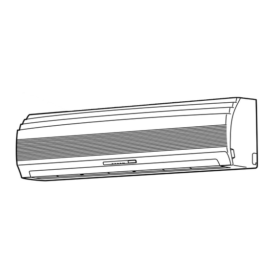
SERVICE MANUAL
AIR CONDITIONER
RAS-13UKHP-E3 / RAS-13UAH-E3
RAS-10UKHP-E3 / RAS-10UAH-E3
RAS-07UKHP-E3 / RAS-07UAH-E3
RAS-13UKP-E3 / RAS-13UA-E3
RAS-10UKP-E3 / RAS-10UA-E3
RAS-07UKP-E3 / RAS-07UA-E3
RAS-13UKPX3 / RAS-13UAX3
RAS-10UKPX3 / RAS-10UAX3
RAS-07UKPX3 / RAS-07UAX3
RAS-12UKPX3 / RAS-12UAX3
FILE NO. SVM-04004-3
SPLIT WALL TYPE
Revised on Oct, 2005
Advertisement
Table of Contents
Troubleshooting


Need help?
Do you have a question about the RAS-13UKHP-E3 and is the answer not in the manual?
Questions and answers
ne svjetli mi zelena lampica. uređaj ne radi. napajanje je o.k.