
Related Manuals for Morgana DigiFold Pro


Summary of Contents for Morgana DigiFold Pro
- Page 1 DigiFold Pro DOCUMENT FOLDING MACHINE OPERATORS MANUAL Morgana Systems Limited United Kingdom Telephone: ( 01908 ) 608888 Facsimile: ( 01908 ) 692399 Website: www.morgana.co.uk March 2011 ISSUE 3 174-025...
-
Page 2: Table Of Contents
INDEX INTRODUCTION & SPECIFICATION The Morgana DigiFold Pro PAGE SAFETY Do’s & Don’ts THE Digifold Pro Labeled Photograph THE SWITCH PANEL Detailed diagram and description Features on the switch panel OPERATING THE DigiFold Pro Adjusting the Papergate Setting the Suction Slot... - Page 3 DigiFold Pro INDEX REPLACING CREASING BLADE SETS Installing new blade sets PAGE 38 Spare Blades PERFORATING Equipment, Spares Setting the machine Recommended Position of the Drive Wheels and Hubs REMOVING PAPER JAMS TROUBLE SHOOTING Paper crease out of square Crease Position Inaccuracy...
- Page 4 DigiFold Pro INTRODUCTION AND SPECIFICATION Digifold Pro is a registered trade mark of Morgana systems Ltd. The unique patented creasing and folding system, makes it possible to fold most delicate stocks from 0.11mm, up to 0.4mm thick. The DigiFold Pro...
-
Page 5: Safety Do's & Don'ts
DigiFold Pro Safety Do’s & Don’ts Safety Do’s & Don’ts REGLES DE SECURITE : « A FAIRE » ET « A NE PAS FAIRE » Do - read this operator manual fully before operating the machine. Lire ce mode d'emploi avant d'utiliser la machine. - Page 6 Warning Labels Do - be aware of any finger traps and rotating parts when operating the machine. Attention au risque de se coincer les doigts, et aux pièces en mouvement lors du fonctionnement de la machine. Do - read this operator manual fully before operating the machine. Lire ce mode d’emploi avant d’utiliser la machine.
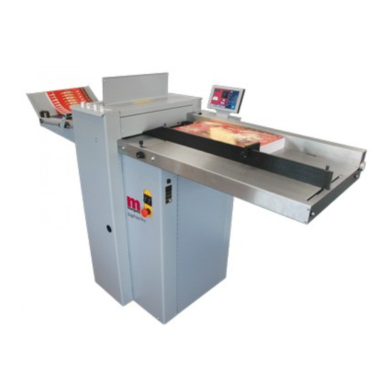
- Page 7 DigiFold Pro DigiFold Pro DOCUMENT FOLDING MACHINE Key to photograph below Delivery assembly 6 Air Separation Knob 11 Paper Gate Vacuum bleed knob 7 Adjustable side lay 12 Top cover Suction slot knob 8 Back stop 13 Touchscreen Switch panel...
- Page 8 The Switch Panel The Switch Panel houses the Compressor switch, System switch, and an industry standard Emergency Stop switch which will stop all power going to the machine when activated. THE SWITCH PANEL Compressor Switch System Switch Emergency Stop Switch Page 8 FOLDING...
-
Page 9: Features On The Switch Panel
DigiFold Pro The Switch Panel Features on the Switch Panel System switch When activated the system switch will operate the motors in order to begin the creasing sequence. Compressor switch Allows the operator to switch off the compressor unit in order to utilise the machine to manually feed sheets. -
Page 10: Operating The Digifold Pro Adjusting The Papergate
Operating the DigiFold Pro Adjusting the Paper Gate Set the height of the Paper Gate to approximately two thicknesses of paper, by turning the disc j. An excessive gap is a most likely cause of double sheet feeding. This setting is only intended as a guide, for instance, sheets with an upward curl will require this setting to be increased. -
Page 11: Setting The Vacuum Bleed
DigiFold Pro Operating the DigiFold Pro Setting the Vacuum Bleed Situated on the front of the feed table, the Vacuum Bleed Knob is used to allow more control of the suction on the vacuum drum. When light weight paper is being fed through the machine turn the knob clockwise to reduce the possibility of marking, or damage to the leading edge of the paper. - Page 12 Operating the DigiFold Pro Setting the positions of drive wheels and hubs It is important that the drive wheels and drive hubs, on the roller shafts, are arranged across the width of the media being creased; this is done to ensure that the media is accurately driven and supported through the rollers.
- Page 13 DigiFold Pro Operating the DigiFold Pro BLANK PAGE SYSTEM Page 13...
- Page 14 Select the green tick icon only if you have been trained to operate this machine. If you have not been trained to operate this machine and you select the green tick icon, Morgana Systems Ltd accept no responsibility for personal injury, damage to the machine or damage to materials being processed by the machine.
-
Page 15: Paper Settings
DigiFold Pro Operating the DigiFold Pro Setting Pages. Paper settings Page Fold Selection - For quick setting of fold positions on standard size sheets. Highlighted fold is type currently selected, other folds may be selected. Paper Type - As a guide choose as Currently selected fold is shown in the status area. - Page 16 Operating the DigiFold Pro Batch size Selection. Pre-set Batch sizes for quick insertion. Paper Thickness input Paper Thickness Selection. Pre-set Paper Thickness sizes for quick insertion. Page 16 FOLDING...
-
Page 17: Roller Gap Set & Tilt Mechanism
DigiFold Pro Operating the DigiFold Pro Roller Gap Set & Tilt Mechanism Page. To get to the roller gap setting page click the lower tab Roller gaps may be in the range of 0.05mm to 1.5mm, with increments of 0.05mm... - Page 18 Operating the DigiFold Pro The gap settings (Gap 1, Gap 2 & Gap 3) can then be adjusted by rotating the Roller Gap Set Knobs (see FIG 10.1 on page 10). IMPORTANT. When setting roller gaps, you must first adjust the gap to a value greater than that required and then decrease the value to the required setting.
- Page 19 DigiFold Pro Operating the DigiFold Pro Setting the Blade Tilt Mechanism The blade tilt mechanism has been designed to compensate for when the creasing position on the sheet is not square. This could be due to an inaccuracy in the media or if the blade tilt mechanism has been incorrectly set.
-
Page 20: Creases In 'Set By Fold' Mode
Operating the DigiFold Pro Crease Settings Pages. To get to the crease setting page click the lower tab from the status area. If you have selected a predefined standard Fold Type from the paper settings page ± 0.1mm the crease positions will be set for you. These positions can be fine tuned by increments by pressing the arrow buttons for each crease. -
Page 21: Creases In 'Set By Position' Mode
DigiFold Pro Operating the DigiFold Pro Creases in ‘Set By Position’ mode. Arrows may be selected Crease position - On selection the to increase or decrease status area is replaced with a The page size in 0.1mm calculator for inputting new values, a increments maximum of 9 creases can be added. - Page 22 Operating the DigiFold Pro Turn crease on/off. Status shows creasing off Greyed out area indicates icon the trim is not selectable This button toggles creasing on & off. Individual deletion of crease confirmation screen. Crease 230 mm from lead edge will be deleted.
-
Page 23: Folds In 'Set By Fold' Mode
DigiFold Pro Operating the DigiFold Pro Fold Settings Pages. To get to the Fold setting page click the lower tab from the status area. If you have selected a predefined standard Fold Type from the paper settings page ± 0.1mm the crease positions will be set for you. -
Page 24: Folds In 'Set By Position-' Mode
Operating the DigiFold Pro Folds in ‘Set By Position’ mode. Fold distance from lead edge for knives (K1 & K2) increments of 0.1mm K1 deflect button K1 micro adjust selected Clicking this icon switches K1 in deflect position. deflect off &K1 returns to its original position. - Page 25 DigiFold Pro Operating the DigiFold Pro NOTES:- If a crease position is adjusted, the fold will move with it. If a fold position is adjusted, then only the fold will move. Adjust a fold only if the fold appears to be giving an out of square result or cracking appears.
- Page 26 Operating the DigiFold Pro Example of Set by Position. Paper Length = 350mm (13.8”) Feed Direction Leading Edge Crease 1 Crease 2 Crease 3 SETTINGS Fold 1 Fold 2 Crease 1 = 97.0mm (3.8”) Crease 2 = 179.0mm (7”) Crease 3 = 260.0mm (10.2”) All dimensions are from the leading edge of the paper Fold 1 = 179.0mm (7”)
-
Page 27: Delivery Settings
DigiFold Pro Operating the DigiFold Pro Delivery Settings Page. To get to the Delivery setting page click the lower Roller position may be micro adjusted by clicking here. Shingle may be micro adjusted by clicking here. Roller adjustment calculator. Shingle adjustment calculator. - Page 28 Operating the DigiFold Pro Setting the Delivery Conveyor System. WARNINGS:- 1. The Machine will start if the delivery unit is not in its up position. 2. If the delivery is turned off the roller will feed to the far end of the belt conveyor and park there until turned on again.
-
Page 29: Status Screen
DigiFold Pro Operating the DigiFold Pro Status Screen. Green icon indicates settings are Clicking in this area will take Clicking in this area will take saved - a red icon would show that you to the paper setting you to the store page settings have changed but page. - Page 30 Operating the DigiFold Pro Run Job. Click to run machine. System Switch Not On. Click to confirm System switch is on & then click run button again The machine running screen will appear. Run count Batch Count Job Count Click to stop machine.
-
Page 31: Setting The Machine To Operate In Manual Sheet Feed Mode
DigiFold Pro Operating the DigiFold Pro Setting the machine to operate in manual sheet feed mode In order to feed heavy stock, very small or very large sheets, embossed or even irregular shaped sheets, it may be necessary to feed the sheets manually. -
Page 32: Store
Operating the DigiFold Pro Store Pages. To get to the Store setting page click the lower tab from the status area. New Jobs. Having set up your job you can give the job a name and save it to a store. You can also retrieve previously saved jobs, modify them or delete jobs you no longer require. - Page 33 DigiFold Pro Operating the DigiFold Pro Save confirmation screen. To confirm saving of job click here. Search for current jobs to load or modify. You can search for jobs by clicking the search icon , this will bring up the search keyboard for text input.
- Page 34 Operating the DigiFold Pro Loading job confirmation screen. To cancel loading of Job press here To confirm loading of Job press here Loaded job may be modified and then re-saved as the same job name. Overwrite job confirmation screen. To cancel overwrite of Job press here.
-
Page 35: Tools Menu
DigiFold Pro Operating the DigiFold Pro Tools Menu. To get to the Tools page click the lower tab Click on Up Arrow to put Anvil into Top Dead Centre position Inch paper in direction (TDC) of arrow to clear jams... - Page 36 Operating the DigiFold Pro BLANK PAGE Page 36 FOLDING...
- Page 37 DigiFold Pro The Blade Assembly Adjusting the blade pressure (no paper required) 1. (i) Switch the power ‘on’ by turning the Emergency stop button clockwise to release the safety latch. (ii) Select the Tools tab at the bottom of the touch screen, the display will change to that shown below.
- Page 38 Replacing Blade Sets 1. Before removing the blade assembly, ensure that the lower blade / anvil is at ‘Top Dead Centre’, see page 37. 2. Lift the top cover. 3. Using a 5mm allen key, remove the two socket head screws, one each end of the Blade Set, as shown in FIG 32.1 below.
- Page 39 DigiFold Pro Replacing Blade Sets 6. Insert the Blade Extractor Tools, one at each end of the Blade Set, as shown in FIG 33.1 below. Note The Position of The Blade Extractor Tool Under The Lip of The Blade Adjuster Assembly FIG 33.1...
- Page 40 Replacing Blade Sets 8. Slide the blade assembly out of the creasing unit and lay it on a flat surface. 9. Slide the blade adjustment cams and the blade adjustment assemblies away from the dowels located in the ends of the blades / anvils as shown in FIG 34.1 below. FIG 34.1 10.
- Page 41 Blade sets are individually set for each machine at the point of manufacture. Replacement Blade sets will therefore need to be set up by a factory trained service engineer. Do not attempt to use a Blade set from another Digifold Pro. SYSTEM Page 41...
- Page 42 Perforating Once the machine is set-up, the Machine can be used to perforate or crease. Notes 1. Perforating and creasing can be carried out simultaneously. However, if any adjustment is made to the roller tilt mechanism in order to compensate for the perforation line being ’out of square’, this may effect the accuracy of the crease.
-
Page 43: Setting The Machine
DigiFold Pro Perforating All of the blades and anvils are supplied with fixings. *Perforator stripper Standard Part Number 177-05-01 *It is recommended that for multiple perforations, a separate perforator stripper is used for every perforating blade set fitted in the creasing unit. - Page 44 Perforating 12. Slide the drive hub towards the perforating drive wheel until there is a clearance of 0.5mm (0.020”). 13. To prevent damage to the blades or the anvils, do not force the drive wheel against the hub. 14. Fix the perforator stripper adjacent to the drive wheel and blade as shown. 15.
-
Page 45: Removing Paper Jams
DigiFold Pro Removing Paper Jams Removing Paper Jams In the event of a paper jam occurring, whilst running the machine, follow the steps described below to allow access to remove the jammed paper. 1. Unlock and lower the delivery unit, open the top cover and the perforator unit; see FIG 39.1 below. - Page 46 BLANK PAGE Page 46 FOLDING...
-
Page 47: Crease Position Inaccuracy
DigiFold Pro Trouble Shooting Paper crease out of square Check that the sheets are all square and exactly the same size before loading the stack on to the table. Check that the adjustable side lay has been correctly positioned ie. No further than 0.5mm (0.020”) from the paper stack. -
Page 48: Machine Will Not Start
Trouble Shooting Machine will not start Check the power supply to the machine. Check that the emergency stop button has been released. Check that the top cover is down. Check that the perforator assembly is in its closed position. Check that the delivery unit is in the up position, and located correctly, (the machine will not start if the delivery unit is not in its up position). -
Page 49: Using The Correct Blade Set
DigiFold Pro Trouble Shooting Using the Correct Blade Set. Two Blade sets are supplied with the machine. The Standard Blade set is suitable for material thicknesses of 0.25mm (0.010”) and greater. The Narrow Blade set is suitable for material thicknesses of 0.25mm (0.010”) and smaller. -
Page 50: Paper Crunch
Trouble Shooting Error Screens Sheet did not arrive. If the machine stops and error message 01 is displayed on the touch screen, this indicates that the paper did not arrive at the end of the suck process; so the machine timed out. -
Page 51: Blade Busy
DigiFold Pro Trouble Shooting Error Screens (Continued) Blade Busy If the machine stops and error message 05 is displayed on the touch screen, this indicates that the blade is busy. Try to operate the machine again, If this fails it is advised to contact a Service Engineer. -
Page 52: Flying Home Failure
Trouble Shooting Error Screens (Continued) Flying Home Failure If the machine stops and error message 08 is displayed on the touch screen, this indicates that the home signal was missed during creasing. Check that the blade pressure is not too high. Clip 1 NOT clear (Back Sensor) If the machine stops and error message 09 is displayed on the touch screen, this... -
Page 53: Clip 2 Not Blocked
DigiFold Pro Trouble Shooting Error Screens (Continued) Clip 2 NOT Blocked (Top Sensor) If the machine stops and error message 12 is displayed on the touch screen, this indicates that the sensor did not see the paper at the correct time. -
Page 54: Trouble Shooting
Trouble Shooting Recommended weekly operator maintenance Clean all sensors. The lead edge sensor housing is located on the layedge side of the machine between the input roller shafts. With a slim brush the sensors can be cleaned when required. Pass the brush under the ball holder and push through until it passes the infeed rollers. - Page 55 DigiFold Pro BLANK PAGE SYSTEM Page 55...
-
Page 56: Dispatch Kit
170-95-02 DISPATCH KIT ITEM PART NUMBER DESCRIPTION OPERATORS MANUAL - 174-025 DigiFold Pro 90-018 ROLLER CLEANING KIT 650-040 POWER CORD C19 UK 16A 2.5m 170-009-01 BLADE REMOVAL TOOL 601-167 DIGITAL THICKNESS GAUGE SCREW - SOCKET CAP HEAD - M3 x 6 LG... -
Page 57: Accessories And Options
NARROW SHEET KIT 173-169-01 ETHERNET KIT 176-213-03 DYNAMIC BLADE SET - ULTRA NARROW 178-01-02 STACKER ASSEMBLY - DIGIFOLD PRO ACCESSORIES..OPTIONS..May be obtained from ..May also be obtained and your dealer and fitted to your fitted by your dealer. You should... -
Page 58: Recommended Spares
RECOMMENDED SPARES PART NO. DESCRIPTION 125-21-02 Dual Stepper Driver Board 125-25-01 Small Stepper Driver - High Power 174-06-01 Small Stepper Driver - Low Power 174-01-02 Controller PCB Assembly + Chip 174-19-01 RS232 Adaptor PCB Assy. 75-472-01 Mini ITX Motherboard (Configured) 126-059-02 Link - Paper Guide 128-026-03 Delivery Belt... -
Page 59: Recommended Spares
DigiFold Pro RECOMMENDED SPARES PART NO. DESCRIPTION 172-05-01 Paper Gate Assembly 175-21-01 Vacuum Roller Assembly 176-02-01 Blade Adjuster Assembly 176-081-01 Worm Wheel - Gap Set 176-213-01 Dynamic Blade Set - Narrow 176-213-02 Dynamic Blade Set - Standard 177-01-01 Perforator Assembly... - Page 60 MACHINE CALIBRATION HISTORY Serial Number:- Date:- Total Count:- Vac Suck Trim Vac Park Trim Stretch Lead Edge Trim Follow Stretch Del. Roller Trim Knife 1 Trim Knife 2 Trim K1 Deflect Trim K2 Deflect Trim K1 Travel K2 Travel Date:- Total Count:- Vac Suck Trim Vac Park Trim...
-
Page 61: Fuse Positions & Ratings
DigiFold Pro FUSE POSITIONS & RATINGS (POSITION ET CLASSIFICATION DES FUSIBLES) PSUs (24V & 48V) PSU (5V / 24V) (FUSIBLE PSUs (24 V & 48 V) (FUSIBLE PSU (5V/24 V) T6.3AH 250 (681-019) F3.15AH 250 (613-023) SPARE FUSE ANTI-STATIC UNIT... - Page 62 PRODUCT RECYCLING & DISPOSAL European Union Disposal Information for Commercial Users Application of this symbol on your equipment is confirmation that you must dispose of this equipment in compliance with agreed national Procedures. In accordance with European legislation end of life electrical and electronic equipment subject to disposal must be managed within agreed procedures.
- Page 63 DigiFold Pro SYSTEM Page 61...
Need help?
Do you have a question about the DigiFold Pro and is the answer not in the manual?
Questions and answers
The delivery service damaged the machine's monitor and I see that it has a terminal for an Enternet card. Is it possible to connect it to a computer to replace the control monitor?
No, the Morgana DigiFold Pro uses a proprietary PRO control system with a Linux-based operating system that runs only the machine control program. The control system includes a VGA touch screen display and other dedicated hardware components. There is no mention of connecting an external computer to replace the control monitor.
This answer is automatically generated