
Related Manuals for Morgana AutoFold Pro


Summary of Contents for Morgana AutoFold Pro
- Page 1 184-019 Issue 4 FEBRUARY 2013 AutoFold Pro (CB/UL) SERVICE MANUAL Document Folding Machine Morgana Systems Limited United Kingdom www.morgana.co.uk Telephone: ( 01908 ) 608888 Facsimile: ( 01908 ) 692399...
-
Page 2: Introduction
MORGANA Autofold Pro i ..Introduction The purpose of this manual is to explain the procedure for dis- mantling and re-assembly of the major assemblies on the Morgana Autofold Pro machine. All the engineering adjustments are shown at the end of each relevant section. -
Page 3: Identification
Autofold Pro Pan head and Cross-head countersunk screws all have metric Taptite threads and Pozi-drive recesses. Use No.2 point Pozidriv or Supadriv drivers for all screws M4 & above, and No.1 point drivers for M3 & below. WARNING WORK SHOULD BE CARRIED OUT BY A TRAINED AND COMPETENT ENGINEER AND ALL SAFETY PROCEDURES SHOULD BE ADHERED SWITCH OFF MAINS POWER BEFORE COMMENCING. -
Page 4: Table Of Contents
INDEX Introduction ………………………………………………………………………..PAGE ¡ Introduction ..............2 ¡¡ Fasteners ..............2 ¡¡¡ Identification ..............3 New Machine Preparation ..........3 Section A …… Covers………….…..............Operator and Lay edge Side Doors....... 9 Rear Cover..............9 Operator and Lay edge Columns ......... 10 Top Cover Assembly ............ 10 Delivery Conveyor Removal......... - Page 5 Autofold Pro PAGE Section G …...Removing / Replacing Fold Knife Assembly………………. ……........Upper Fold Knife............27 ..........Bottom Fold Knife............27 Section H …..Main Fold Rollers Removal………………………….............Removal Third Fold Roller...........28 ..........Removal Second/First Fold Roller.......29 ..........Main Fold Rollers - Replacement .......30 ENGINEERING SET-UP &...
- Page 6 Section 15 ....Test Run ................60 Section M .....Trouble Shooting ......................Folding Unit............61 ..........For Error Messages refer to Operator manual..63 Section N .....Circuit Diagrams ......................AutoFold Pro Wiring Diagram........64 ..........Control PCB Connection Diagram......65 ..........Fuse Positions & Ratings........66 Page 6 FOLDING...
- Page 7 Autofold Pro BLANK PAGE SYSTEM Page 7...
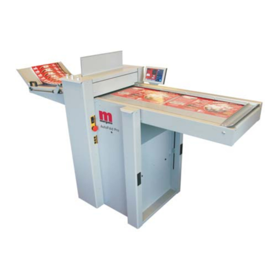
- Page 8 Autofold Pro DOCUMENT FOLDING MACHINE Key to photograph below Delivery assembly Fixed Sidelay Top Cover Vacuum Table Lay Side Door Input Guide Touchscreen Op. Side Door Fuses Switch panel Column Lay Side Gap Sets Column Op. Side Page 8 FOLDING...
-
Page 9: Operator And Lay Edge Side Doors
Autofold Pro SECTION A Covers: The Operator Side Door. The Operator Side Door cover which is situated adjacent to the operator, covers the Gap Set mechanism and small stepper boards. To remove this cover, first remove the two top fixing screws attaching the top plate, this must be lifted upwards to clear the gap set adjuster Knobs. -
Page 10: Operator And Lay Edge Columns
SECTION A The Operator and Lay side Columns The Operator and lay side column doors conceal the Gas struts for the Feed Bed. To remove the doors open them up using the handles provided and remove the six screws securing the hinge to the main frame. To replace is the reverse procedure. -
Page 11: Delivery Conveyor Removal
Autofold Pro SECTION A A.6 Delivery Conveyor To Remove the Delivery Conveyor the rear cover should be removed for access. Pivot the delivery down at 45 degrees using the handle on the end and turn the ‘delivery locking screw’ anti-clockwise to lock the delivery strut into this position. Shown in photo below. -
Page 12: Section B .......Feed Bed
SECTION B Feed Bed Accessing the Fans and control board Remove the two Pan Heads securing the input guide to the end of the bed. (be carefull not to lose the spacer they secure). With the Guard removed Unscrew the Countersunk Screws in the Feed bed. Lift off the bed. -
Page 13: Removal Of Feed Bed
Autofold Pro SECTION B Removal of Feed Bed unit Remove the top panel of the Feed Bed as previously explained. With access to the fan control board remove the connections to the rest of the machine. Now remove the Latches on either side of the bed near the operator and lay doors. -
Page 14: Section C .......Infeed Roller Removal/Replacement
SECTION C REMOVAL/REPLACEMENT OF INPUT ROLLERS All side covers and the top cover should be removed to ease access to the infeed rollers. TOP INPUT ROLLER Remove the lead edge sensor housing by unscrewing the two fixing screws from the rear of the machine and leave loose in situ. - Page 15 Autofold Pro Layedge Side Operator Side SYSTEM Page 15...
-
Page 16: Section D .......Replacing The Touchscreen Assembly
SECTION D Replacing the Touch Screen Assembly Ensure the mains power is turned off but with the plug in the socket, this maintains an earth to reduce static damage. 1. Open the hinged Lay Side Cover to expose the ITX board. 2. -
Page 17: Section E
SECTION E ELECTRICS: The PRO Control System. The Morgana PRO control system is essentially a computer system just like the PC you use at home. Unlike your Microsoft Windows PC, the PRO system uses a LINUX operating system and runs only one program, which is the machine control program for the particular machine that it is installed on. -
Page 18: Removal/Refitting Control Pcb And Prog Board
SECTION E ELECTRICS: REMOVAL/REFITTING PCB’s REPLACEMENT OF MAIN CONTROL P.C.B. This PCB controls all functions of the machine and houses the Main Program PCB. The use of an antistatic wrist band should be used during work on the main control PCB. Switch the mains power off and disconnect from the mains supply. -
Page 19: Removal/Refitting Usb Flash Drive
Autofold Pro SECTION E REPLACEMENT OF PROCESSOR BOARD. This Small PCB is plugged onto the face of the Main Control PCB and houses the Program Chip. The use of an antistatic wrist band should be used during work on this Processor PCB. - Page 20 Installation Procedure. 1. Note the current machine calibration settings. 2. Power down the machine and remove the power cord. 3. Change the USB Flash Drive (Red or Green depending on what is currently fitted). NOTE. It is important to choose the right colour in accordance with the machine you are upgrading.
- Page 21 Autofold Pro BLANK PAGE Page 21 SYSTEM...
-
Page 22: Removal/Replacement Itx Boards
SECTION E ELECTRICS: REMOVAL/REFITTING PCB’s ITX BOARD REPLACEMENT. The ITX mother board supplies the graphics to the touch screen display, to remove.- 1. Switch the mains power off. 2. Cut cable ties and unplug all the plugs. 3. Unscrew the four fixing screws attaching the board to the plate and remove from the machine. -
Page 23: Entering Engineers Tools
Autofold Pro SECTION E DIAGNOSTICS and CALIBRATION TOOLS. To enter the engineers tools menu. Turn the Machine on. Insert the Engineers Plug into the Socket located at the rear of the machine. Select Tools on the Display and continue to select required tool. -
Page 24: Section F
The lead edge sensor housing is located on the layedge side of the machine between the input roller shafts. See the Autofold Pro Operators Manual (184-018), Trouble Shooting section, for instructions of how to clean the Lead Edge Sensors; and the Clean Lead Edge Sensor Warning screens. -
Page 25: Changing Sensors - Leading Edge
Autofold Pro SECTION F Changing Sensors Lead Edge Sensor The Lead edge sensor assembly is positioned just after the input rollers and is housed in a black delrin machined block. To check the operation of this sensor, insert a piece of paper between the rollers and feed by hand until the sensor is covered, at which point the Red LED3 will illuminate on the main control PCB. -
Page 26: Changing Sensors - Folder Unit Clip 1&2
SECTION F Changing Sensors on the Folder unit Clip Sensors. There are two sets of Clip sensors and both are located just after a set of fold rollers. They act as machine cutouts in cases of malfunction within the folding cycle. Clip 1 &... - Page 27 Autofold Pro SECTION G REMOVING/ FITTING OF FOLD KNIFE ASSEMBLIES Remove the gap set assembly. Upper Fold Knife Remove the top curved guide by unscrewing the four posi pan head screws (2 each end). Loosen the sensor and allow to hang freely. Unscrew the two countersunk head screws (one each end) using a 4mm allen key and remove screws.
- Page 28 SECTION H Main Fold Rollers - Removal The folding unit has 3 main folding rollers that can be easily removed for replacement, the procedure for removing the rollers is as follows:- Rollers cannot be removed without removing the fold knives. Remove rear cover assembly and top guard.
- Page 29 Autofold Pro SECTION H Main Fold Rollers - Removal Remove The 2nd Fold Roller Assembly as follows:- Remove the worm wheel from the shaft. Remove 3 off screws on access housing and 1 off on link plate. The roller assembly can now be withdrawn from the lay side of the machine.
- Page 30 SECTION H Main Fold Rollers - Replacement. The main rollers should be fitted into the folding unit in the reverse order of removal. Procedure for replacing the rollers is as follows:- Replace The 1st Roller Assembly as follows:- Insert the roller assembly into the frame from the operator side of the machine. Replace screws to lock hub in position.
- Page 31 Autofold Pro BLANK PAGE SYSTEM Page 31...
- Page 32 Autofold Pro Engineering Set-Up & Calibration Techniques Generally, Pre-Power Set-Up is made much easier if the Top Cover and the Entry Guard are removed. An adequate supply of Test Sheets (Part Number 170-004-01) should be made available for many of the set-up procedures.
- Page 33 Autofold Pro SYSTEM Page 33...
- Page 34 Vacuum Table Installment:- The Autofold Pro is packaged with the Vacuum Table folded into a vertical position. Use the following procedure to fix the Vacuum Table into its operating position. 1.1. Ensure the Lower Gas Strut Eyes and the Support Stud Knob are loose.
- Page 35 Autofold Pro To allow for manufacturing tolerances, the squareness of the Vacuum Table Assembly is controlled by the location plate on the inside of the main frame on the operator side of the machine. Use the following procedure to check & adjust the Loading Table squareness:- Open the Input Roller gap fully by releasing the Locking Screw using a 4mm hexagon key to 1.6.
- Page 36 If adjustment is required, loosen the six Pan head screws securing the location plate. 1.9. Adjust the Vacuum Table so that the lead edge of the sheet is parallel to the upper input roller. Ensure the location plate is located around the position of the support disk and tighten the four screws on the location plate.
- Page 37 Autofold Pro Belt Tension:- There are 3 Drive belts on the Autofold Mechanism & 3 on the Delivery system. All Drive belts are XL Series Timing Belts of various widths and should be tensioned in accordance with the following notes.
- Page 38 Upper Input Roller - Setting the Parallelism & Pressure The Upper Input Roller is gear driven from the Lower Input Roller & should be adjusted for parallelism & pressure to ensure sheets are correctly aligned and controlled On the Layside end of this roller, there is an eccentric housing which enables adjustment. The housing is secured to the shaft using two M5 flat tip set screws.
- Page 39 Autofold Pro FIG.3.1.B Shaft Flats 80gsm Test Strips Adjust the Layside Housing, using the shaft flats on the operator side, until a light 3.2. pressure is felt on the operator strip & then temporarily tighten one of the housing set screws on the op side. (the top one).
- Page 40 Fold Rollers - Setting the Parallelism & Pressure There are four Fold Rollers, one of which is fixed (Ø45) and has no adjustments This roller acts as the datum for the remaining three Fold Rollers (Ø60) which all have parallelism & pressure adjustments to ensure sheets are correctly aligned and controlled On the Layside end of each roller is an eccentric housing which enables adjustment of the parallelism.
- Page 41 Autofold Pro SYSTEM Page 41...
- Page 42 Setting The Fold Knives. The Fold Knives are driven by a stepper motor and is controlled by a cam follower and cam profile. The position of the black delrin cam is critical as it controls the start & stop positions of the Fold Knives.
- Page 43 Autofold Pro downwards until the jig assembly fits correctly, adjust the 5.4. Rotate the Delrin cam eccentric shaft if required, tighten the two cap head screws on the ends of the eccentric shaft. Remove the Right Hand Shoulder Bolt from the Setting Jig, rotate the Jig (and the Knife 5.5.
- Page 44 6. Adjusting The Top Cover safety Switch 6.1. Open layside door. 6.2. Loosen the two fixings on the switch. 6.3 Adjust the switch position until lifting the top cover switches the machine when lifted by 6mm - 10mm. Page 44 FOLDING...
- Page 45 Autofold Pro SYSTEM Page 45...
- Page 46 Powered Setup Procedure. The "Powered Set-Up Procedure" does require connection to the Mains Power Supply so please ensure that all Covers & Guards are replaced & secure before proceeding. Adjustments to the Control System & Circuit Boards should only be carried out by fully trained & qualified personnel.
- Page 47 Autofold Pro Fold Roller Gap Potentiometers:- The Fold Roller Gaps are controlled by a mechanism which uses potentiometers to measure their positions. This information is then available to the Operator on the Gap Set Screen. These 3 Pots, which are located at the bottom of the Gap-Set Mechanism on the Operator Side of the machine, will all require calibrating:- Enter the Gap-Set Screen by operating the Touch screen.
- Page 48 Sensors and Detectors:- The Autofold is equipped with a total of four Sensors & two Detectors. They all have indicator LED's on the Main Control Board & their operation can be checked from the Advanced Tools Menu. The sensitivity of the Sensors can be adjusted individually by adjusting the appropriate Potentiometer on the Main Control Board using a small insulated electrical screwdriver.
- Page 49 Autofold Pro Crunch Sensor uses a beam projected across the machine just in front of the blade and above the paper path, when the beam is broken the machine will stop. The receiver is housed in the Side Plate of the machine and is on the Operator Side, whilst the transmitter is housed in the Side Plate of the machine on the Lay Side.
- Page 50 Delivery Assembly The Delivery Assembly is there to provide a moving platform for the processed sheets to collect onto once finished. It consist of 2 main components, the delivery belt, and the delivery roller. Delivery Belt 10.1. To set the delivery Belt tension correctly it is imperative that the 2 'Roller Drive Belts' are first loosened to prevent excessive loads to the drive roller bearings.
- Page 51 Autofold Pro Ensure the eccentric idlers are rotated to give little or no tension to the delivery 10.1.4. roller drive belts. Eccentric Idler (1 Each Side) FIG.10.1.4 Raise the delivery until it is fully up (ensure the gearbox is engaged first).
- Page 52 The 'Delivery Roller' drive belts need to be tensioned correctly (see previous section). NOTE - When adjusting the tension of the Lay Side 'Delivery Roller Drive Belt', notice that you are also providing the tension for the motor drive for this roller. Delivery Roller Squareness 10.2.1.
- Page 53 Autofold Pro 10.2.2. Delivery Potentiometer To position the roller correctly there is a potentiometer which provides the feedback to the processor. In order to set this correctly, you must follow this procedure; 10.2.2.1. Raise the delivery until it is fully up .
- Page 54 10.2.2.5. Whilst holding the belt away from the pulley carefully rotate the potentiometer pulley until it reaches the end of its travel. 10.2.2.6. Continue to hold the belt away from the pulley and rotate the potentiometer pulley in the opposite direction for a full 5 turns (use a mark for reference if required).
- Page 55 Autofold Pro Fold Set up Procedure POWERED SETUP PROCEDURE POWER UP AUTOFOLD SET FOLD ONLY TO RUN TEST SHEET AND NOTE 100 & 250 SOFTWARE VERSION SET FOLD ONLY ADJUST K1 & K2 POSITIONS HALF FOLD ON K1 FOLD TRIMS...
- Page 56 Crease & Fold Setup Procedure Having completed the Pre-powered and Powered setup the autofold needs to have the fold positions calibrated. This is primarily conducted using software adjustments within the 'tools' menu, however, during this process you may need to re-adjust the Upper input roller in accordance with the descriptions stated below.
- Page 57 Autofold Pro SYSTEM Page 57...
- Page 58 Calibration This is the final calibration procedure and closely follows the 'Calibration' flow chart. You must have completed all previous setup procedures leading up to this final calibration. If additional information is required for setting up the various crease and fold variations, please refer to the operators manual.
- Page 59 Autofold Pro Deflect Adjustments The deflect trims need to be calibrated to allow the sheet to pass through the machine without damaging the lead edge. 14.1 K1 Double Deflect Trim In the tools menu Conduct this test with K2 turned off using the 'Tools' menu.
- Page 60 Test Run (i) From the Home screen on the Display, select a Fold Type (ii) Select 'Fold’ On. (iii) Following the procedure laid out in the Operators Manual, set up and run each of the folds listed in the 'Set Type' screen and examine the results. (iv) If adjustment is required, refer to the 'Engineering Set-Up and Calibration Techniques section of this Service Manual.
- Page 61 Autofold Pro Section M Trouble Shooting Folding Fault Reason Solution Folding out of square Folding too close to crease. Move fold further away. with crease Crease blade too wide for Change creasing blade set for stock thickness. narrow blade set.
- Page 62 2. CHECK THE ITX MOTHER BOARD AS FOLLOWS:-. (i) Remove the 3V lithium disc battery from the ITX mother board and check the voltage using a multi meter. If the voltage is less than 1.5V replace the ITX mother board. If the voltage is more than 1.5V refit the battery to the board.
- Page 63 IMPORTANT. If this fuse has blown it must be replaced with a T500mA fuse, Morgana part number 681-020. (230V 50Hz Machines only) T1A fuse, Morgana part number 681-021. (110V 60Hz Machines only). Is there a V DC output from the ATX PSU? (See page 61).
- Page 64 Section N Page 64 FOLDING...
- Page 65 Autofold Pro PSU ASSY. (76-310) ENGINEERING LEAD (76-292) DRIVE SIGNAL LEAD (76-298) 25 SENSOR BAR ASSY. (175-11-05) DELIVERY INPUT CONNECTOR LEAD (76-302) 26 SENSOR BAR ASSY. (175-11-04) SYSTEM SWITCH COIL LEAD (76-284) 30 FOLD KNIVES SENSOR (76-304) GAP SET 1 LEAD (76-305)
- Page 66 FUSE POSITIONS & RATINGS TRANSFORMER ASSY. (230V 50Hz MACHINES) T500mAH 250V (681-020) TRANSFORMER ASSY. (110V 60Hz MACHINES) T1AH 250V (681-021) PSUs (24V & 48V) (FUSIBLE PSUs (24 V & 48 V) T6.3AH 250V (681-019) ANTI-STATIC UNIT (FUSIBLE ANTI-STATIQUE) T315mAH 250V (681-011) MAINS IN FUSE T15AH 250V (652-047) MAINS INPUT...
- Page 67 Autofold Pro REVISION HISTORY Rev. Mod No. Mod Description Date Mod By Note at the bottom of Page 18 added, reference the position of switch SW1 when fitting a new Main Control PCB. Page 24; see Autofold Operators Manual (184-018) for Lead Edge Sensor...
Need help?
Do you have a question about the AutoFold Pro and is the answer not in the manual?
Questions and answers