Table of Contents
Advertisement
Quick Links
Advertisement
Table of Contents

Related Manuals for d&b audiotechnik Vi


Summary of Contents for d&b audiotechnik Vi
- Page 1 Rigging manual (1.2 EN)
-
Page 2: General Information
General information Rigging manual Version: 1.2 EN, 08/2013, D2708.EN .01 Copyright © 2013 by d&b audiotechnik GmbH; all rights reserved. Keep this manual with the product or in a safe place so that it is available for future reference. When reselling this product, hand over this manual to the new customer. -
Page 3: Table Of Contents
2.4. Rear/Splay links of the frames......... 14 2.5. Cabinet's rigging mechanism........16 2.5.1. Front link mechanism..........16 2.5.2. Splay/Rear link mechanism........17 2.5.3. Setting splay angles for Vi-TOP cabinets..... 17 Arrays and assembly..........18 3.1. Setup preparation............. 19 3.2. Vi8/Vi12 Array............19 3.3. -
Page 4: Safety
Z5387.000 Vi Mounting frame top The Vi Mounting frame top is designed to suspend smaller arrays of Vi-TOP or Vi-SUB cabinets with a total system weight of up to 136 kg (300 lb) - SWL, which corresponds to a total weight of up to 4 x Vi-TOP cabinets. -
Page 5: Wind Loads
The additional safety device must be mounted in a way that the array is caught by the safety device without any drop and swing in the event that the primary suspension fails. d&b Vi Rigging manual (1.2 EN) -
Page 6: Operational Safety
When chain hoists are in operation ensure that there is nobody directly underneath or in the vicinity of the load. Do not under any circumstances climb on the array. d&b Vi Rigging manual (1.2 EN) -
Page 7: Rigging Concept And Components
2.1. Mounting and flying frames The d&b Vi loudspeakers are supplemented by two mounting frames, the Z5387.xxx Vi Mounting frames, one for the top and one for the bottom of an array. These frames allows the setup of the following array configurations: d&b Vi Rigging manual (1.2 EN) -
Page 8: Z5387.000 Vi Mounting Frame Top
Rear link including Fixing bolt [3a] and Ring cotter [3b]. In connection with the Front links of the Vi loudspeaker cabinets, the Rear link of the frame is used to attach the frame to the first cabinet of an array. -
Page 9: Z5387.001 Vi Mounting Frame Bottom
SUB cabinets in mixed array configurations with the Z5380 V Flying frame mounted on top of the array. This allows a maximum of up to 4 x Vi-TOP cabinets to be attached underneath SUB cabinets. Note: A detailed description of the Z5380 V Flying frame... - Page 10 Scope of supply Please verify the shipment for completeness and proper condition of the items. The Z5387.001 Vi Mounting frame bottom is equipped and supplied with the following rigging components. Note: In delivered condition, the Rear link [3] and the O-ring [4] are not attached to the frame.
-
Page 11: Dimensional Drawings
2.1.3. Dimensional drawings Fig. 2: Z5387.001 Vi Mounting frame bottom, Fig. 1: Z5387.000 Vi Mounting frame top, dimensions in mm [inch] dimensions in mm [inch] d&b Vi Rigging manual (1.2 EN) -
Page 12: Ring Cotters
2.2. Ring cotters In connection with the Vi rigging system, ring cotters are used for the following items to prevent the respective item from slackening and/or loosening: – Fixing bolt of the TOP and SUB cabinet's Rear links. – Fixing bolt of the frame's Rear links and cable picks. -
Page 13: Locking Pins
Mounting/Flying frames. Ensure all Locking pins are fully inserted and securely locked before lifting any load. The Vi loudspeaker cabinets are equipped with two types of Locking pins: Type [B] Locking pin 9 x 40 mm. -
Page 14: Rear/Splay Links Of The Frames
[C]. Splay/Rear link positions The position of the frame's Rear link depends on the type of cabinet (Vi8/Vi12 or Vi-SUB) that is to be attached to the corresponding Mounting frame. In connection with the bottom frame, observe the direction of attachment as shown below in Fig. - Page 15 Fig. 7 and Fig. 8. 2. Insert the Fixing bolt. 3. Insert and lock the Ring cotter. Changing the Splay/Rear link position on Vi Mounting frames To change the Rear link position, follow the previous assembly instructions in reverse order. The procedure for the top frame is described as an example.
-
Page 16: Cabinet's Rigging Mechanism
2. Insert and lock one Locking pin to fix the link in place. Fig. 9: Front link mechanism of Vi8/Vi12 cabinets Vi-SUB cabinets The Front link mechanism of the Vi-SUB cabinets provides four different settings: a. SUB to Frame (Þ Fig. 11) b. -
Page 17: Splay/Rear Link Mechanism
0° to 14° in 1° steps. The splay angles are set at the central rear rigging strands of the cabinets. Vi8/Vi12 cabinets The Splay link of the Vi-TOP cabinets is designed as a straight link with two holes. The inner hole defines the splay angle while the outer elongated hole is used for the second Locking pin (Safety pin [S]) as shown in the graphic opposite. -
Page 18: Arrays And Assembly
For assembly instructions, please refer to: For assembly instructions, please refer to: Þ Chapter 3.2. "Vi8/Vi12 Array" on page 19 Þ Chapter 3.3. "Vi-SUB Column" on page 22 Fig. 19: Mixed array For assembly instructions, please refer to: Þ Chapter 3.4. "Mixed array" on page 25... -
Page 19: Setup Preparation
In combination with the Z5387.000 Vi Mounting frame top, a maximum of 4 x Vi-TOP cabinets can be flown. To fly more than 4 x Vi-TOP cabinets, the Z5380 V Flying frame must be used. In this case, please follow the assembly instructions given in the V- Series Rigging manual, which is supplied with the V Flying frame. - Page 20 7. Insert the first Locking pin to fix the angle and cabinet in place. 8. Insert the second Locking pin (Safety pin). To add further cabinets, proceed in the same manner until the [7°] assembly is completed. d&b Vi Rigging manual (1.2 EN)
- Page 21 4. Attach the bottom frame The Z5387.001 Vi Mounting frame bottom is used if the application requires the array to have an overall vertical angle that is not covered by ArrayCalc or cannot be obtained by the intended suspension. The bottom frame allows the attachment of additional steel wire ropes or hoists.
-
Page 22: Vi-Sub Column
In connection with the Z5387.000 Vi Mounting frame top, a maximum of 2 x Vi-SUB cabinets can be flown. For more than 2 x Vi-SUB cabinets, the Z5380 V Flying frame must be used. In this case, please follow the assembly instructions given in the V- Series Rigging manual which is supplied with the V Flying frame. - Page 23 7. Fold out the Rear link of the upper cabinet. 8. Reinsert the Locking pin on the upper cabinet. 9. Fold the Rear link into the rigging strand of the bottom cabinet. 10. Reinsert the two Locking pins on the bottom cabinet. d&b Vi Rigging manual (1.2 EN)
- Page 24 4. Attach the bottom frame for pullback purposes The Z5387.001 Vi Mounting frame bottom is used if the application requires the array to have an overall vertical angle that is not covered by ArrayCalc or cannot be obtained by the intended suspension.
-
Page 25: Mixed Array
For the second frame, there are two options depending on the number of TOP cabinets to be mounted: – Up to 4 x Vi-TOP cabinets can be mounted underneath the SUB cabinets using the Z5387.001 Vi Mounting frame bottom in addition to the V Flying frame. - Page 26 1. Release and remove the Locking pin of the Splay link at park position and fold out the Splay link. 2. Unlock and remove the ring cotter of the fixing bolt. 3. Pull out the fixing bolt and remove the Splay link. d&b Vi Rigging manual (1.2 EN)
- Page 27 2. Insert the second Locking pins of the cabinet's Front links on both sides. 3. On the rear rigging strand of the cabinet, release both Locking pins. 4. Fold the Splay link into the rigging strand and reinsert the Locking pins. d&b Vi Rigging manual (1.2 EN)
- Page 28 9. Fold the Rear link into the rigging strand of the bottom cabinet. 10. Reinsert the two Locking pins on the bottom cabinet. 5. Attach the Vi Mounting frame bottom The Rear link of the bottom frame must be attached to the SUB position.
- Page 29 Splay link of the frame ("Z5387.001 - Pos. 3B"). Þ Attach the Splay link to the frame correspondingly. To add futher TOP cabinets, proceed in the same manner as described in Þ Chapter 3.2. "Vi8/Vi12 Array" on page 19. d&b Vi Rigging manual (1.2 EN)
- Page 30 7. Attach a further bottom frame for pullback purposes The Z5387.001 Vi Mounting frame bottom is used if the application requires the array to have an overall vertical angle that is not covered by ArrayCalc or cannot be obtained by the intended suspension.
- Page 31 8. Check the assembly Before hoisting the array to its operating position, recheck the actual status of the entire assembly according to the checklist given in Þ Chapter 4. "Safety and system checks" on page 32. d&b Vi Rigging manual (1.2 EN)
-
Page 32: Safety And System Checks
If the amplifiers are already wired and powered on, use their System check functions or Channel mute switches and a test signal to check the correct operation and routing of all channels and cabinets. d&b Vi Rigging manual (1.2 EN) -
Page 33: Hoisting And Aiming The Array
5.2. Modifying the vertical aiming of the array The Z5387.001 Vi Mounting frame bottom is used if the application requires the array to have an overall vertical angle that is not covered by ArrayCalc or cannot be obtained by the intended suspension. -
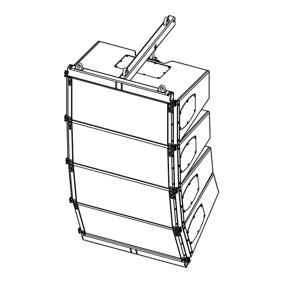
Page 34: Dedicated Fixing Points
5.2.1. Dedicated fixing points Fig. 21: Vi8/Vi12 array 4-deep Fig. 22: Vi-SUB column 2-deep Fig. 23: Vi-SUB assembly Fig. 24: Vi8/Vi12 array 12-deep d&b Vi Rigging manual (1.2 EN) -
Page 35: Care And Maintenance / Disposal
When out of use the rigging components must be disposed of in accordance with the national environmental regulations. Ensure that damaged rigging components are disposed of in a way that they cannot be used again. d&b Vi Rigging manual (1.2 EN) -
Page 36: Manufacturer's Declaration
Z5380.901, V Flying frame SC National standards and technical specifications applied: DIN EN ISO 12 100, DIN EN 1050, DIN EN 18 800-1, BGV C1. Backnang, 2013-07-23 Frank Bothe, Head of R&D d&b audiotechnik GmbH d&b Vi Rigging manual (1.2 EN) - Page 37 www.dbaudio.com...
Need help?
Do you have a question about the Vi and is the answer not in the manual?
Questions and answers