
Related Manuals for Electra LS 35


Summary of Contents for Electra LS 35
- Page 1 CENTRAL AIR CONDITIONER SPLIT SYSTEM WITH ELECTRONIC CONTROL SERIES LS INSTALLATION INSTRUCTIONS...
-
Page 2: Table Of Contents
SUMMARY GENERAL................................1 SELECTING THE LOCATION OF UNITS......................3 RELATIVE LOCATION OF THE UNITS......................3 SELECTING THE OUTDOOR UNIT (CONDENSER) LOCATION..............3 SELECTING THE INDOOR UNIT (EVAPORATOR) LOCATION ..............4 INSTALLATION OF THE INDOOR UNIT (THE EVAPORATOR) ..............5 INSTALLATION OF THE INDOOR UNIT......................5 CONDENSATE DRAIN PIPING OF THE INDOOR UNIT................. -
Page 3: General
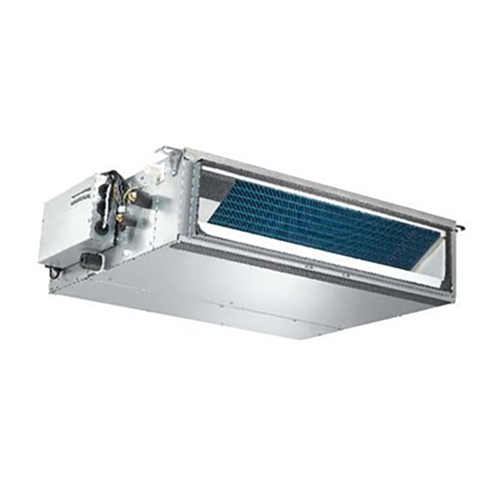
1. GENERAL The installation instructions relate to LS air-conditioners. LS air-conditioners are made up of two units: an indoor unit (evaporator) and an outdoor unit (condenser). The two units are interconnected by two refrigerant tubes, an electric cable and a control cable. Below are recommendations for correct installation of apartment air-conditioner systems: •... - Page 4 LS Indoor Unit (Evaporator) LS 35/40/55 LS 65/85 1. Flare coupling 5. Condensate Drain Port 2. Fresh air intake Ø 100 and Ø 125 6. Air inlet 3. Filter 7. Air outlet 4. Electrical component box 250x190x70 LS Outdoor Unit (Condenser) 1.
-
Page 5: Selecting The Location Of Units
2. SELECTING THE LOCATION OF UNITS Only trained and qualified service personnel recommended by the company should install the air conditioner, in pursuance of the company specifications and using pipes, wiring, and the standard installation accessories of the company. Any service call, maintenance or repair carried out by the company on equipment that was installed in noncompliance with the company's instructions will require payment. -
Page 6: Selecting The Indoor Unit (Evaporator) Location
2.3 Selecting the indoor unit (evaporator) location Take into account the following requirements when selecting the place of the indoor unit: • Allow maximum air diffusion, to as great as possible a distance within the space to be air- conditioned. •... -
Page 7: Installation Of The Indoor Unit (The Evaporator)
3. INSTALLATION OF THE INDOOR UNIT (THE EVAPORATOR) 3.1 Installation of the indoor unit (see fig. 2) A. The indoor unit is designed for installation inside the building in a place not exposed to outdoor conditions. B. When it is necessary to install the unit outside the building or in a roof space, take the following steps: •... -
Page 8: Condensate Drain Piping Of The Indoor Unit
3.2 Condensate drain piping of the indoor unit • It is recommended to have a professional plumber prepare a drain outlet having a 32 mm diameter rigid PVC tube near the indoor unit, to which a flexible drain pipe for the drainage of the indoor unit can be attached. -
Page 9: Outdoor Unit Installation
4. OUTDOOR UNIT INSTALLATION Installation on flat surface (roof, ground, etc.) The outdoor unit should be elevated at least 100 mm above the ground by using concrete pad, concrete blocks or wooden beams, in order to allow free flow of condensate water (See Figure 5). 200 mm 1500 mm Figure 5: Outdoor Unit Installation Criteria... -
Page 10: Connection Of Refrigerant Tubing Between Indoor And Outdoor Units
(it is forbidden to insert a tube into another tube) between the flare connection and the unit’s branch pipes. UNIT MODEL REFRIGERANT TUBING LENGTH UP TO IN METERS MAX HEIGHT LINE DIFFERENCE LS 35 Suction 1/2” Liquid 1/4” LS 40 Suction 1/2” 1/2” Liquid 1/4”... -
Page 11: Recommendations For Refrigerant Tubing Installation
Recommendations for refrigerant tubing installation There are three possible variants, a shown on the diagrams: 1. The outdoor unit is installed above the indoor unit (Figure 7) - such installation requires an oil trap in the suction line at the lowest point of the riser. The radius of the oil trap should be as short as possible (see Figure 8). -
Page 12: Flare Preparation
5.3.1 Flare preparation 90º Cut the tube, using a tube cutter. Make sure that the cut is perpendicular to the tube axis and free of burrs (see Figure 11). Slip the flared nut over the tube, secure the tube in the flaring tool, as shown in Figure 12 and perform the flare on the tube end. - Page 13 1. Charging set 2. Vacuum pump 3. Outdoor unit 4. Service port 5. Valve cap 6. Suction valve 7. Valve cap 8. Liquid valve 9. Indoor unit 10. Suction flare connection 11. Liquid flare connection NOTE: 1. For additional refrigerant charge, for various tubing lengths refer to outdoor unit nameplate.
-
Page 14: Electrical Connections
10. Remote ON/OFF Switch (by Installer) 5. Indoor unit 11. Control Cable 6. Quick-attach coupling Figure 15: Single Phase Units – Indoor Supply: Electrical Scheme MODEL CIRCUIT BREAKER LS 35 10 A LS 40 16 A LS 55 16 A LS 65... - Page 15 1. Outdoor unit 7. Display control unit 2. Inter connecting cable 8. Wireless Remote Control 3. Power Supply 9. Wired Remote Control (optional) 4. Semi-automatic switch 10. Remote ON/OFF Switch (by Installer) 5. Indoor unit 11. Control Cable (Shielded) 6. Display Quick connector 12.
-
Page 16: Interconnecting Cable
1. Outdoor unit 8. Wireless Remote Control 2. Inter connecting cable 9. Wired Remote Control (optional) 3. Power Supply 10. Remote ON/OFF Switch (by Installer) 4. Semi-automatic switch 11. Control Cable (Shielded) 5. Indoor unit 12. Switch ON/OFF (by Installer) 6. -
Page 17: Display Control Unit
Display control unit 6.3.1 Location criteria It is recommended to install the Display Control Unit close to a ceiling in a central and neutral zone at typical conditions. In addition, the aesthetic aspect should be considered. The Display Control Unit is connected to the main control board on the air conditioner (the indoor unit) by a communication cable. -
Page 18: Remote-Controller Mounting
1. Main Control Board on Indoor Unit, Cat. N. 402616 and 402676 2. Distribution Board, Cat N. 402729 3. Communication cable Cat. N. 402730 4. Display Control Unit N. 1 Cat. N. 402713 5. Display Control Unit N. 2 Cat. N. 402713 6. -
Page 19: Final Tasks
7. FINAL TASKS Replace all caps and covers and check that they are well shut. Seal all the cracks and holes at the sides of the tubes and bores. Attach the wiring and tubes to the wall with clamps. Check all the operations of the air-conditioner. If necessary, use the operating manual. Indoor unit −... - Page 20 CENTRAL AIR CONDITIONER SPLIT SYSTEM WITH ELECTRONIC CONTROL SERIES LS INSTALLATION INSTRUCTIONS...
- Page 21 SUMMARY GENERAL................................3 SELECTING THE LOCATION OF UNITS......................5 RELATIVE LOCATION OF THE UNITS......................5 SELECTING THE OUTDOOR UNIT (CONDENSER) LOCATION ..............5 SELECTING THE INDOOR UNIT (EVAPORATOR) LOCATION ..............6 INSTALLATION OF THE INDOOR UNIT (EVAPORATOR) ................7 INDOOR UNIT LOCATION ..........................7 CEILING MOUNTING............................8 CONDENSATE DRAIN PIPING OF THE INDOOR UNIT ..................9 OUTDOOR UNIT INSTALLATION ........................10 CONNECTION OF REFRIGERANT TUBING BETWEEN INDOOR AND OUTDOOR UNITS .......11 GENERAL.................................11...
-
Page 22: General
1. GENERAL The installation instructions relate to LS air-conditioners. LS air-conditioners are made up of two units: an indoor unit (evaporator) and an outdoor unit (condenser). The two units are interconnected by two refrigerant tubes, an electric cable and a control cable. Below are recommendations for correct installation of apartment air-conditioner systems: •... - Page 23 INDOOR UNIT (Evaporator) Figure 1 Dimensions (mm) LS 90 LS 105 LS 125 1. Air Supply 5. Filters 1100 1100 1185 2. Electrical Box 6. Access Panel 1140 3. Refrigeration Tubing 7. Control Unit Port Port 8. Main Power 1105 4.
-
Page 24: Selecting The Location Of Units
2. SELECTING THE LOCATION OF UNITS Only qualified service personnel trained by the company should install the air conditioner. The installation will be performed in pursuance of the company specifications and using pipes, wiring, and the standard installation accessories of the company. Any service call, maintenance or repair carried out by the company on equipment that was installed in noncompliance with the company's instructions will require payment. -
Page 25: Selecting The Indoor Unit (Evaporator) Location
2.3 Selecting the indoor unit (evaporator) location Take into account the following requirements when selecting the place of the indoor unit: • Allow maximum air diffusion, to as great as possible a distance within the space to be air- conditioned. •... -
Page 26: Installation Of The Indoor Unit (Evaporator)
3. INSTALLATION OF THE INDOOR UNIT (EVAPORATOR) 3.1 Indoor Unit Location (See Figure 3) The indoor unit is designed for installation on a false ceiling or other compartment, where there is no influence from outdoor conditions. While selecting the location, the following conditions must be assured: The location should assure free flow of the return air into the unit without interference. -
Page 27: Ceiling Mounting
2. The minimum height clearance for the installation is 370 mm. 3. A minimum distance of 200 mm must be kept between the rear side of the unit and any near-by wall, to allow free air passage. 4. A minimum distance of 300 mm must be kept to allow free air intake and convenient access to air filters. 5. -
Page 28: Condensate Drain Piping Of The Indoor Unit
3.3 Condensate drain piping of the indoor unit • It is recommended to have a professional plumber prepare a drain outlet having a 32 mm diameter rigid PVC tube near the indoor unit, to which a flexible drain pipe for the drainage of the indoor unit can be attached. -
Page 29: Outdoor Unit Installation
4. OUTDOOR UNIT INSTALLATION Installation on flat surface (roof, ground, etc.) The outdoor unit should be elevated at least 100 mm above the ground by using concrete pad, concrete blocks or wooden beams, in order to allow free flow of condensate water. (See Figure 7). 200 mm 1500 mm Figure 7: Outdoor Unit Installation Criteria... -
Page 30: Connection Of Refrigerant Tubing Between Indoor And Outdoor Units
5. CONNECTION OF REFRIGERANT TUBING BETWEEN INDOOR AND OUTDOOR UNITS 5.1 General (See Figure 8) The indoor and outdoor units are connected by two copper tubes and an 1. To outdoor unit electric cable, all passed through a 60- 2. Connecting tubing mm wall opening. -
Page 31: Recommendations For Refrigerant Tubing Installation
5.2 Recommendations for refrigerant tubing installation There are three possible variants, a shown on the diagrams: The outdoor unit is installed above the indoor unit (Figure 9) - such installation requires an oil trap in the suction line at the lowest point of the riser. The radius of the oil trap should be as short as possible (see Figure 10). -
Page 32: Flare Preparation
5.3.1 Flare preparation 90º Cut the tube, using a tube cutter. Make sure that the cut is perpendicular to the tube axis and free of burrs (see Figure 13). Slip the flared nut over the tube, secure the tube in the flaring tool, as shown in Figure 14 and perform the flare on the tube end. - Page 33 1. Charging set 2. Vacuum pump 3. Outdoor unit 4. Service port 5. Valve cap 6. Suction valve 7. Valve cap 8. Liquid valve 9. Indoor unit 10. Suction flare connection 11. Liquid flare connection NOTE: 1. For additional refrigerant charge, for various tubing lengths refer to outdoor unit nameplate.
-
Page 34: Electrical Connections
6. ELECTRICAL CONNECTIONS Power Supply WARNING Electrical connection shall be made only by authorized electricians and in accordance with local electrical requirements and codes. The system must be grounded. Single-phase models and three phase models are available; for each of them, the necessary wiring diagram is shown. -
Page 35: Interconnecting Cable
1. Outdoor unit 8. Wireless Remote Control 2. Inter connecting cable 9. Wired Remote Control (optional) 3. Power Supply 10. Remote ON/OFF Switch (by Installer) 4. Semi-automatic switch 11. Control Cable (Shielded) 5. Indoor unit 12. Switch ON/OFF (by Installer) 6. -
Page 36: Display Control Unit
Display control unit 6.3.1 Location criteria It is recommended to install the Display Control Unit close to a ceiling in a central and neutral zone at typical conditions. In addition, the aesthetic aspect should be considered. The Display Control Unit is connected to the main control board on the air conditioner (the indoor unit) by a communication cable. -
Page 37: Remote-Controller Mounting
1. Main Control Board on Indoor Unit, Cat. N. 402616 and 402676 2. Distribution Board, Cat N. 402729 3. Communication cable Cat. N. 402730 4. Display Control Unit N. 1 Cat. N. 402713 5. Display Control Unit N. 2 Cat. N. 402713 6. -
Page 38: Final Tasks
7. FINAL TASKS Replace all caps and covers and check that they are well shut. Seal all the cracks and holes at the sides of the tubes and bores. Attach the wiring and tubes to the wall with clamps. Check all the operations of the air-conditioner. If necessary, use the operating manual. 4.1 Indoor unit −...