
Related Manuals for Electra LS DCI Series


Summary of Contents for Electra LS DCI Series
- Page 1 LS DCI Series Indoor Units Outdoor Units LS 35 DCI ONG3-35 DCI REFRIGERANT R410A HEAT PUMP OCTOBER – 2008 SM LS DCI 1-E.1 GB CONTENT...
- Page 2 LIST OF EFFECTIVE PAGES LIST OF EFFECTIVE PAGES Note: Changes in the pages are indicated by a “Revision#” in the footer of each effected page (when none indicates no changes in the relevant page). All pages in the following list represent effected/ non effected pages divided by chapters.
- Page 3 TABLE OF CONTENTS Table of Contents INTRODUCTION ....................1-1 PRODUCT DATA SHEET ..................2-1 RATING CONDITIONS ..................3-1 OUTLINE DIMENSIONS ..................4-1 PERFORMANCE DATA & PRESSURE CURVES ..........5-1 AIRFLOW CURVES ....................6-1 ELECTRICAL DATA ....................7-1 WIRING DIAGRAMS .....................8-1 REFRIGERATION DIAGRAMS ................9-1 10. TUBING CONNECTIONS ..................10-1 11.
- Page 4 INTRODUCTION INTRODUCTION General The new LS DCI 35 ducted Unit is another completion to the DC inverter units range, Which includes several types such as wall mounted, floor /ceiling, cassettes, and multi splits. Main Features The LS DCI 35 benefits from the most advanced technological innovations, namely : DC Inverter Technology.
- Page 5 INTRODUCTION Control The microprocessor indoor controller, and an infrared remote control, supplied as standard, provide complete operating function and programming. For further details please refer to the Operation Manual, Appendix A. Outdoor Unit The ONG35 DCI outdoor unit can be installed as floor or wall mounted by using a wall supporting bracket.
- Page 6 INTRODUCTION Matching Table R410A INDOOR UNITS OUTDOOR UNITS MODEL REFRIGER. WNG25 WNG35 PXD25 PXD35 LS 35 DCI √ √ √ ONG25 DCI R410A √ √ √ ONG35 DCI R410A √ The above table lists outdoor units and LS DCI indoor unit which can be matched together. In addition the listed outdoor units can be matched with other types of indoor units such as cassettes and wall mounted.
- Page 7 PRODUCT DATA SHEET PRODUCT DATA SHEET LS 35 DCI / ONG 35 DCI R410A LS 35 DCI Model Indoor Unit ONG 35 DCI Model Outdoor Unit Installation Method of Pipe Flared Characteristics Units Cooling Heating Btu/hr 11940(5118-15686) 14663(5118-18760) Capacity 3.5(1.5-4.6) 4.3(1.6-5.5) Power input 0.96 (0.42-1.45)
- Page 8 RATING CONDITIONS RATING CONDITIONS Rating conditions in accordance with ISO 5151 and ISO 13253 (for ducted units). Cooling: Indoor: C DB 19 C WB Outdoor: 35 C DB Heating: Indoor: C DB Outdoor: 7 C DB 6 C WB Operating Limits 3.1.1 R410A Indoor...
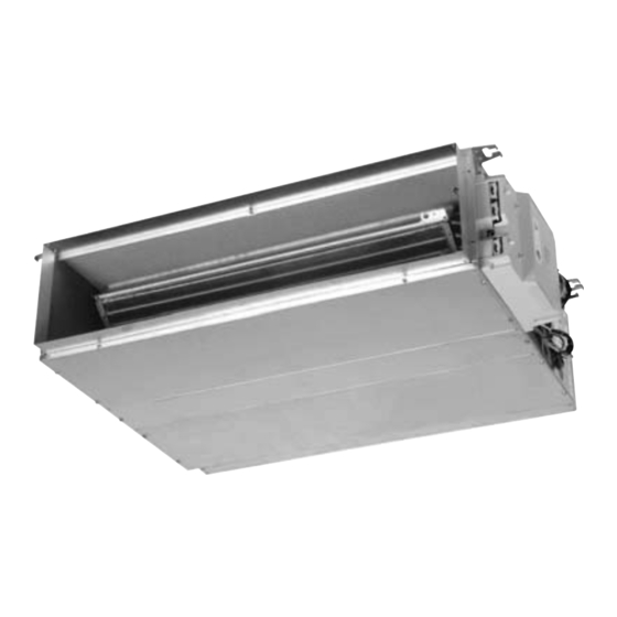
- Page 9 OUTLINE DIMENSIONS OUTLINE DIMENSIONS Indoor Unit: LS 35 DCI Outdoor Unit: ONG3-35 DCI SM LS DCI 1- E.1 GB CONTENT...
- Page 10 PERFORMANCE DATA & PRESSURE CURVES PERFORMANCE DATA LS 35 DCI 5.1.1 Cooling Capacity (kW) - Run Mode 230[V] : Indoor Fan at High Speed. ID COIL ENTERING AIR DB/WB TEMPERATURE [ OD COIL ENTERING AIR DB 22/15 24/17 27/19 29/21 32/23 DATA TEMPERATURE [...
- Page 11 PERFORMANCE DATA & PRESSURE CURVES 5.1.3 Heating Capacity (kW) - Run Mode) 230[V] : Indoor Fan at High Speed ID COIL ENTERING AIR DB TEMPERATURE [ OD COIL ENTERING AIR DB/WB DATA TEMPERATURE [ 2.74 2.55 2.35 -15/-16 0.80 0.89 0.97 3.05 2.86...
- Page 12 PERFORMANCE DATA & PRESSURE CURVES 5.1.5 Capacity Correction Factor Due to Tubing Length LS 35 DCI: Cooling 1.01 1.00 0.99 0.98 0.97 0.96 0.95 0.94 0.93 0.92 0.91 9 10 11 12 13 14 15 16 17 18 19 20 Tubing Length [m ] 5.1.6 Heating...
- Page 13 PERFORMANCE DATA & PRESSURE CURVES Pressure Curves 5.2.1. Model: LS 35 DCI Cooling — Test Mode Suction Pressure Vs.Outdoor Temp. 1400 Indoor 1300 DB/WB 1200 22/15 1100 24/17 1000 27/19 29/21 32/23 Outdoor DB Temperature [ºC ] Discharge Pressure Vs.Outdoor Temp. 4000 3750 Indoor...
- Page 14 PERFORMANCE DATA & PRESSURE CURVES 5.2.2. Heating — Test Mode Suction Pressure Vs.Outdoor Temp. 1300 1200 indoor DB 1100 1000 Outdoor WB Temperature [ºC] Discharge Pressure Vs.Outdoor Temp. 4000 3750 3500 Indoor DB 3250 3000 2750 2500 2250 2000 1750 1500 1250 1000...
- Page 15 AIRFLOW CURVES AIRFLOW CURVES Model: LS 35 DCI Airflow Vs. External Static Pressure LS 35 DCI The System characteristics defines Super High recommended motor speeds range High vs.static pressure Medium Nominal System Resistance Max.System Resistance Operating range Curve's colors according to fan motor wires colors Point for Performance test 1000...
- Page 16 ELECTRICAL DATA ELECTRICAL DATA Single Phase Unit MODEL LS 35 DCI To indoor Power Supply 1PH-230V-50Hz Max Current, A Inrush Current A Starting Current A 10.5 Circuit Breaker A Power Supply Wiring No. X 3x1.5 mm Cross Section mm Interconnecting Cable No. X 4x1.5 mm Cross Section mm (a) Inrush current is the current when power is up (charging the DC capacitors...
- Page 17 WIRING DIAGRAMS WIRING DIAGRAMS Model: LS 35 DCI SM LS DCI 1- E.1 GB CONTENT...
- Page 18 REFRIGERATION DIAGRAMS REFRIGERATION DIAGRAMS Heat Pump Models 9.1.1 LS 35 DCI SM LS DCI 1- E.1 GB CONTENT...
- Page 19 TUBING CONNECTIONS TUBING CONNECTIONS TUBE (Inch) ¼” ⅜” ½” ⅝” ¾” TORQUE (Nm) Flare Nuts 11-13 40-45 60-65 70-75 80-85 Valve Cap 13-20 13-20 18-25 18-25 40-50 Service Port Cap 11-13 11-13 11-13 11-13 11-13 Valve Protection Cap-end Refrigerant Valve Port (use Allen wrench to open/close) Valve Protection Cap Refrigerant Valve Service Port Cap...
- Page 20 CONTROL SYSTEM CONTROL SYSTEM 11.1 General Functions and Rules (for single split models) The DCI software is fully parametric. All the model dependent parameters are shown in Blue color and with Italic style [parameter]. The parameters values are given in the last section of this control logic chapter of the service manual.
- Page 21 CONTROL SYSTEM Target Frequency Setting 11.3.2 The compressor target frequency is a function of the NLOAD number sent from the indoor controller and the outdoor air temperature. Basic Target Frequency Setting: NLOAD Target Frequency Maximum frequency 10 < NLOAD < 127 Interpolated value between minimum and maximum frequency Minimum frequency Compressor is stopped...
- Page 22 CONTROL SYSTEM 11.4 Indoor Fan Control 10 Indoor fan speeds are determined for each model. 5 speeds for cool/dry/fan modes and 5 speeds for heat mode. When user sets the indoor fan speed to a fixed speed (Low/ Medium/ High), unit will operate constantly at set speed.
- Page 23 CONTROL SYSTEM Outdoor Fan Speed Compre Routine A Routine B Routine C Routine D CF = 0 Very Low OFLowFreq 10 ” CF < Medium Very Low OFLowFreq OFMedFreq ” CF < High Medium OFMedFreq ” CF In cooling mode, the extra rule is as the below: Change To Higher OFAN Cool state (*1) Change To lower...
- Page 24 CONTROL SYSTEM 11.9 Ionizer Control Ionizer is on when unit is on AND indoor fan is on AND Ionizer power switch (on Ionizer) is on 11.10 Electro Static Filter (ESF) Control ESF is on when ESF switch is on, Safety switch is pressed, unit is on, AND indoor fan is on.
- Page 25 CONTROL SYSTEM Model J2 Shorted J2 Opened Wall mounted Compensation Disabled Compensation Enabled Cassette Compensation Enabled Compensation Disabled Ducted Compensation Enabled Compensation Disabled Floor/Ceiling Compensation Disabled Compensation Enabled 11.16 Indoor Fan Control in Heat Mode Indoor fan speed depends on the indoor coil temperature: ICTVL ICTL ICTH...
- Page 26 CONTROL SYSTEM Indoor Coil Defrost Protection 11.19.1 ICT Trend Fast Increasing No change Decreasing Fast Increasing Decreasing ICT < -2 -2 ” ICT < 0 0 ” ICT < 2 2 ” ICT < 4 4 ” ICT < 6 Norm Norm 6 ”...
- Page 27 CONTROL SYSTEM Compressor Temperature Control Status Else Increases Norm Stop Compressor Compressor over Current Protection 11.19.4 Stop-Compresor CCROC4 HzDown2 CCROC3 HzDown1 CCROC2 Stop-Rise CCROC1 Normal Heat Sink over Heating Protection (NA for DCI 25 and 35 11.19.5 HST Trend Decreasing No Change Increasing HST >...
- Page 28 CONTROL SYSTEM Outdoor Coil Deicing Protection 11.19.6 Deicing Starting Conditions: Deicing operation will start when either one of the following conditions exist: Case 1: OCT < OAT – 8 AND TLD > DI Case 2: OCT < OAT – 12 AND TLD > 30 minutes. Case 3: OCT is Invalid AND TLD >...
- Page 29 CONTROL SYSTEM 11.20 Condensate Water Over Flow Protection Each of the pins P1, P2, P3 can have two options: 1 – When it is shorted with P4 0 – When it is not shorted to P4 3 Levels Logic (used in floor/ceiling models) 11.20.1 Level L2&3...
- Page 30 CONTROL SYSTEM 1 Level Logic (used in all models except for floor/ceiling models) 11.20.2 Level Don’t Normal care Don’t Overflow care Overflow when Overflow when unit is ON unit is OFF Overflow Water Level Normal OPER BLINK NLOAD is NLOAD forced to 0 PUMP 8 min...
- Page 31 CONTROL SYSTEM 11.23 On Unit Controls and Indicators Indoor Unit Controller Controls and Indicators for All Models 11.23.1 STAND BY INDICATOR Lights up when the Air Conditioner is connected to power and ready to receive the R/C commands Lights up during operation. Blinks for 300 msec., to announce that a R/C infrared signal has been received and stored.
- Page 32 CONTROL SYSTEM 11.25 Test Mode Entering Test Mode 11.25.1 System can enter Test mode in two ways: Automatically when the following conditions exists for 30 minutes continuously: o Mode = Cool, Set point = 16, Room temperature = 27±1, Outdoor temperature = 35±1 o Mode = Heat, Set point = 30, Room temperature = 20±1, Outdoor temperature = 7±1...
- Page 33 CONTROL SYSTEM 11.27 SW Parameters Indoor Units SW Parameters 11.27.1 General Parameters for All Models: Parameters defining the indoor fan speed as a function of Indoor Coil temperature in heat mode (ICT): ICTST Speed ICT to stop indoor fan ICTVLSpeed ICT to go down to very low speed ICTLSpeed ICT to start in very low speed...
- Page 34 CONTROL SYSTEM Outdoor Units SW Parameters: 11.27.2 Parameter Name DCI25 DCI35 DCI 50 DCI50 DUO DCI 60 Compressor Parameters MinFreqC MaxFreqC MinFreqH MaxFreqH Step1Freq Step2Freq Step3Freq Frequency limits as a function of outdoor air temperature MaxFreqAsOATC MaxFreqAsOAT1H MaxFreqAsOAT2H Compressor Over Heating Protection CTTOH1 CTTOH2 CTTOH3...
- Page 35 TROUBLESHOOTING TROUBLESHOOTING WARNING!!! When Power Up – the whole outdoor unit controller, including the wiring, is under HIGH VOLTAGE!!! Never open the Outdoor unit before turning off the Power!!! When turned off, the system is still charged (400V)!!! It takes about 4 Min. to discharge the system. Touching the controller before discharging may cause an electrical shock!!! Single Split system failures and corrective 12.1...
- Page 36 TROUBLESHOOTING SYMPTOM PROBABLE CAUSE CORRECTIVE ACTION Unit works in wrong Check RV power connections, if OK, mode (cool instead of Electronics or power Check RV operation with direct heat or heat instead of connection to RV 230VAC power supply, if OK, cool) Replace outdoor controller.
- Page 37 TROUBLESHOOTING Judgment by Indoor/Outdoor Unit Diagnostics 12.3 Enter diagnostics mode - press for five seconds Mode/Reset button in any operation mode. Acknowledgment is by 3 short beeps and lights of all Display LED’s. Then, The units will enter into Indoor and Outdoor unit diagnostic modes.
- Page 38 TROUBLESHOOTING 12.3.2 Indoor unit diagnosis and corrective actions Fault Probable Cause Corrective Action Check sensor connections or Sensor failures of all replace sensor types Indoor and Outdoor controllers are Replace Indoor controller Communication with different versions mismatch Communication or grounding wiring is Check Indoor to Outdoor wiring No Communication not good.
- Page 39 TROUBLESHOOTING 12.3.4 Outdoor unit diagnosis and corrective actions Probable Cause Corrective Action Fault Sensors failures of all Check sensors connections types or replace sensors. Electronics HW Check all wiring and jumper IPM Fault problem settings, if OK, replace electronics. No action, unless special Bad EEPROM parameters are required for unit operation.
- Page 40 TROUBLESHOOTING 12.5.2 Checking Power Input. If Indoor unit power LED is unlighted, power down the system and check the fuse of the Indoor unit. If the fuse is OK replace the Indoor unit controller. If the fuse has blown, replace the fuse and power up again. Checking Power Input procedure for the Outdoor unit is the same as with the Indoor unit.
- Page 41 EXPLODED VIEWS AND SPARE PARTS LISTS EXPLODED VIEWS AND SPARE PARTS LISTS 13.1 Indoor Unit: LS 35 DCI SM LS DCI 1- E.1 GB 13-1 CONTENT...
- Page 42 EXPLODED VIEWS AND SPARE PARTS LISTS 13.2 Indoor Unit: LS 35 DCI 13-2 SM LS DCI 1- E.1 GB CONTENT...
- Page 43 EXPLODED VIEWS AND SPARE PARTS LISTS 13.3 Indoor Unit: LS 35 DCI Part No. Description Qty. 462350005 COIL LS 035 SP000000094 INSULATED FAN BASE ASSY LS 035/040/055 433316 BRACKET 403439 LT FAN ASSY EBS 50/60,GTW11/18 407038 MOTOR BRACKET FCR/FCX/EBS 438600 REMOTE CONTROL RC RC3 403879 AIR INLET FRAME ASSY LS 035/040/055...
- Page 44 EXPLODED VIEWS AND SPARE PARTS LISTS 13.4 Outdoor Unit: ONG3-25/35 DCI 13-4 SM LS DCI 1- E.1 GB CONTENT...
- Page 45 EXPLODED VIEWS AND SPARE PARTS LISTS 13.5 Outdoor Unit: ONG3-25/35 DCI Part No. Description Unit 433218 Front panel A 4526340 Air inlet ring-420 433223 Painting insulation plate 4526476 Axial fan OD=401 4527092 DC motor for DCI25/35 433215 Motor support 4523060 Base painting Assy.
- Page 46 APPENDIX A APPENDIX A INSTALLATION AND OPERATION MANUAL ► OPERATING MANUAL LS 35 DCI ► INSTALLATION MANUAL LS 35 DCI SM LS DCI 1- E.1 GB 14-1 CONTENT...
Need help?
Do you have a question about the LS DCI Series and is the answer not in the manual?
Questions and answers