Table of Contents
Advertisement
Quick Links
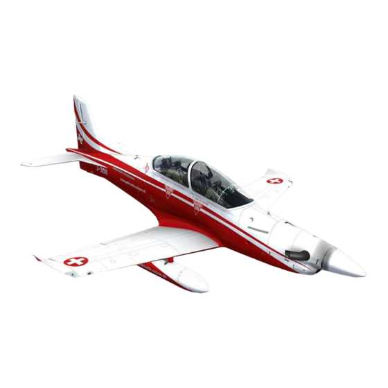
1/4 Scale Almost-Ready-To-Fly RC Model
Spesifications
Scale : 1/4
Length : 112.5": (2850mm)
Weight : 18Kg
Engine : Jetcat SPT5
The PC21 by Skymaster
The 1/4 PC21 produced by Skymaster is the result of years of R&D work and excessive testing. We are proud that
you have decided to buy the best ARF 1/4 PC21 in the market today. We hope you enjoy your PC21 Please note
that the photos show certain views from the prototypes. Some modifications and upgrades might have taken place
by the release of the model. We have tried to produce a very scale replica of this turbo prop. This manual describes
the assembling of " PRO" model. Landing gear and doors are factory installed. Before you start building and set-
ting-up your aircraft, please make sure you have read this instruction manual, and understood it. If you have any
questions, please don't hesitate to contact us. Below are the contact details:
Office Taiwan:
No.15, Min-San 3rd Street, Ren-Wu Area, Kaohsiung, 814, Taiwan, R.O.C.
TEL: +886 9 3299 7923
FAX: + 886 7373 1215
http://www.skymasterjet.com
Sales : skymasterjets@hotmail.com
Technical support : morne.m@pixie.co.za
Assembly and operations manual
SM © 2015
Span
: 90 ": (2288mm)
Radio : 12 Ch (8 servos)
Advertisement
Table of Contents

Related Manuals for Skymaster PC21 Arf Pro


Summary of Contents for Skymaster PC21 Arf Pro
- Page 1 The PC21 by Skymaster The 1/4 PC21 produced by Skymaster is the result of years of R&D work and excessive testing. We are proud that you have decided to buy the best ARF 1/4 PC21 in the market today. We hope you enjoy your PC21 Please note that the photos show certain views from the prototypes.
-
Page 2: Table Of Contents
Assembly & Operation Manual Index: INTRODUCTION............................3 DISCLAIMER..............................3 WARNING…...............................3 ARF PAINT..............................4 FINISHING YOUR MODEL........................4 HANDLING & TRANSPORTING .......................5 TOOL LIST..............................6 HEALTH…..............................7 GENERAL ASSEMBLY TECHNIQUES....................…7 RADIO EQUIPMENT & ACCESSORIES…………….................8 KIT CONTENTS…….…………….......................9 OPTIONAL PARTS………………..………………..................10 WING..……………………………………………………………………………………………………………...11 STABILIZER & RUDDER……......................... 12 FUSELAGE …………………..................,,.... ………..13 FUEL CELLS…………………………………………………………………………………………………...…14 FUEL DIAGRAM………………………….………………………………………………………………………15 AIR SYSTEM ............................ -
Page 3: Introduction
INTRODUCTION Thank you for purchasing Skymaster arf pro pc21 We have put a lot of effort and time into this model. We at Skymaster strive to be a market leader in the ARF— jet market. We were the first company to produce ARF—jets in the world and we would like to continue being amongst the best. -
Page 4: Arf Paint
Assembly & Operation Manual ARF Paint The color finish on your Skymaster PC21 arf pro model was applied out of the mould. We have used only the highest standard automotive paints to finish your model. Should you damage the finish, Skymaster stock the color paint and hardener required for the repair. -
Page 5: Handling & Transporting
Assembly & Operation Manual HANDLING & TRANSPORTING Composite models are very light but strong. These characteristics do have a down side! It is brittle. Take care when handling your model. DO NOT ATTEMPT TO PICK UP AN FULLY FUELED MODEL BY THE LEADING EDGE BY YOURSELF! The leading edges will crack and delami- nate. -
Page 6: Tool List
8. Thread-locking compound (Loctite, or equivalent) At Skymaster we try our best to offer you a high quality kit, with outstanding value-for money, and as complete as possible. However, if you feel that some additional or different hardware should be included, please feel free to let... -
Page 7: Health
The glass cloth side of parts to glue, should be sanded with #80 grit paper for best glue adhesion. Support the fuselage on foam pads. Skymaster makes every attempt to insure that the parts fit. However, due to manufac- turing tolerances, some parts may fit a little tight. Always trial fit parts and adjust if needed. -
Page 8: Radio Equipment & Accessories
Assembly & Operation Manual Radio equipment Failure to use the recommended servos, output arms, extensions, and hardware may result in a loss of control! Throughout this manual we have used JR equipment. If you make use of another manufacturer, please use equipment with similar specifications! The model will require extension leads! Please use high quality extension leads. -
Page 9: Kit Contents
Assembly & Operation Manual Kit Contents Picture A PC21 ARF PRO Contents: Picture A Fuselage front and rear section. Fin + Rudders & engine hatch. Nose gear + Main gear + doors installed Wings left and right + flaps + aileron... -
Page 10: Optional Parts
Assembly & Operation Manual OPTIONAL PARTS 3 x Air Tanks 1 x Retract Valve 2 x Filler & 2 x Pressure Gauges 1 x Electronic Brake Valve 5 x Air Tubing, 10 x Quick Disconnect 8 x T-pieces Photo 2 Fuel Tank Accessory Set Photo 3... -
Page 11: Wing
Assembly & Operation Manual WINGS NOTE: Make sure to have some sort of protective foam on the work bench. This will protect the paint surface from unwanted dents. Assemble both wings simultaneously. Mark √ each step. Photo 9 Photo 11 Photo 10 Use masking tape to keep flap in position. -
Page 12: Stabilizer & Rudder
Assembly & Operation Manual ELEVATORS & RUDDER NOTE: Use some protective foam on the work bench to protect the paint surface from unwanted dents. A removable elevator mechanism is installed. Mark √ each step. Fit servo horn and centre servo using radio. Remove horn. Mark location of horn. Dremel hole to clear horn, refit horn. -
Page 13: Fuselage
Assembly & Operation Manual FUSELAGE Photo 17 Photo 18 Photo 19 Before joining the fuselage it is necessary to tidy up the servo wires. Make sure wires are secure . Tidy up the air line. Use quick disconnects between wing and fuselage. Check operation of landing gear and doors. -
Page 14: Fuel Cells
Assembly & Operation Manual FUEL CELLS NOTE: Bad plumbing lead to flame outs. This will destroy your model. Please take your time and do a good job. Make up fuel line fittings. Make sure clunk moves freely and reaches all corners of inside of tanks. -
Page 15: Fuel Diagram
Assembly & Operation Manual FUEL CELL DIAGRAM Photo 21 P-15... -
Page 16: Air System
Assembly & Operation Manual AIR SYSTEM You will need 2 x 2way and 1x 1way + sequencer. All work done at factory. Glue the air tanks (3) with silicon Use quick connectors on fuselage joints to help with break up of model if glued in tail. Fit the 3 filler valves and 3 pressure gauges onto plywood tray. -
Page 17: Air Diagram
Assembly & Operation Manual AIR DIAGRAM P-17... -
Page 18: Turbine Installation
Assembly & Operation Manual TURBINE INSTALLATION You will need to cut fuselage to clear exhaust of turbo prop. Make sure spinner have enough clearance. Please follow the instructions supplied with your turbo prop. Run all turbine wires and power cables on opposite side of servo wires. Install fuel pump close to UAT. -
Page 19: Cockpit & Canopy
Assembly & Operation Manual COCKPIT AND CANOPY (after painting) Photo 28 Photo 29 Photo 31 Photo 30 Cut cockpit to fit fuselage. Secure rear of cockpit with 2 screws. Check that canopy clear the cockpit. Trim if needed. Install pilot. If you ordered the all white—you will need to cut glass and glue after painting. -
Page 20: Equipment Installation
Assembly & Operation Manual EQUIPMENT INSTALLATION INTO PC21 Equipment installation is a personal venture. There is one golden rule: Do it as neat and logical as possible! This will make fault finding and service of components eas- ier. The pc21 basically consist of 7 circuits! 1. -
Page 21: Before You Fly
Assembly & Operation Manual BEFORE YOU FLY It is assumed that the builder of this kit has acquired the basic skills and knowl- edge necessary to make a safe and functional radio control installation into a model. Therefore, these notes are intended only to assist that experience. TRAVEL MAX SETTINGS: 1. - Page 22 Just before touch down—pull more elevator to flare model. Let the model roll out and apply brakes. Taxi back and do necessary adjustments to customize PC21. We at Skymaster wish you many happy flights with your PC21! Add some landing lights for more realism. Blue skies!
Need help?
Do you have a question about the PC21 Arf Pro and is the answer not in the manual?
Questions and answers