Table of Contents
Advertisement
Quick Links
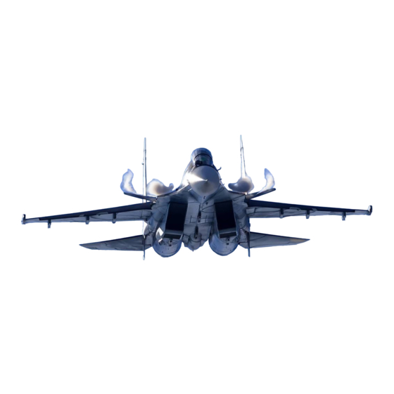
1/6 Scale Almost-Ready-To-Fly RC Jet
Spesifications
Type
: T.A.V.S ARF PRO
Scale : SU30 1/6
Length : 149.5": (3800mm)
Weight : 30Kg
Radio : 18 Ch ( 12servo's)
The SU30 by Skymaster
The 1/6 SU30 produced by Skymaster is the result of years of R&D work and excessive testing. We are proud that
you have decided to buy the best ARF 1/6 SU30 in the market today. We hope you enjoy your SU30! Please note
that the photos show certain views from the prototypes. Some modifications and upgrades might have taken place
by the release of the model. We have tried to produce a very scale replica of the SU30. Many scale options are
included with your model including operating canopy, speed brakes, spoilers and ordinance kit. This manual de-
scribes the assembling of " PRO" model. Opening canopy, speed brakes, landing gear and doors are factory in-
stalled. Before you start building and setting-up your aircraft, please make sure you have read this instruction man-
ual, and understood it. If you have any questions, please don't hesitate to contact us. Below are the contact details:
Office Taiwan:
No.15, Min-San 3rd Street, Ren-Wu Area, Kaohsiung, 814, Taiwan, R.O.C.
TEL: +886 9 3299 7923
FAX: + 886 7373 1215
http://www.skymasterjet.com
Sales : skymaste@skymasterjet.com
Technical support : morne.m@pixie.co.za
Assembly and operations manual
Span
Turbine: 2 x 21kg to 32kg turbines
SM © 2019
: 96.7 ": (2457mm)
Advertisement
Table of Contents

Subscribe to Our Youtube Channel
Related Manuals for Skymaster ARF PLUS PRO SU30


Summary of Contents for Skymaster ARF PLUS PRO SU30
- Page 1 The SU30 by Skymaster The 1/6 SU30 produced by Skymaster is the result of years of R&D work and excessive testing. We are proud that you have decided to buy the best ARF 1/6 SU30 in the market today. We hope you enjoy your SU30! Please note that the photos show certain views from the prototypes.
-
Page 2: Table Of Contents
Assembly & Operation Manual Index: INTRODUCTION............................3 DISCLAIMER..............................3 WARNING…...............................3 ARF PAINT..............................4 FINISHING YOUR SU30 ARF........................4 HANDLING & TRANSPORTING .......................5 TOOL LIST..............................6 HEALTH…..............................7 GENERAL ASSEMBLY TECHNIQUES....................…7 RADIO EQUIPMENT & ACCESSORIES…………….................8 KIT CONTENTS…….…………….......................9 OPTIONAL PARTS………………..………………..................10 SLATS ……………………………………………………………………………………………………….…...12 RUDDER FIN............................14 STABILIZER.............................15 NOSE STEERING AND CANARD..................,,.... -
Page 3: Introduction
INTRODUCTION Thank you for purchasing Skymaster arf pro SU30! We have put a lot of effort and time into this model. We at Skymaster strive to be a market leader in the ARF— jet market. We were the first company to produce ARF—jets in the world and we would like to continue being amongst the best. -
Page 4: Arf Paint
Assembly & Operation Manual ARF Paint The color finish on your Skymaster SU30 arf pro model was applied out of the mold. We have used only the highest standard automotive paints to finish your model. Should you damage the finish, Skymaster stock the color paint and hardener required for the repair. -
Page 5: Handling & Transporting
Assembly & Operation Manual HANDLING & TRANSPORTING Composite models are very light but strong. These characteristics do have a down side! It is brittle. Take care when handling your model. DO NOT ATTEMPT TO PICK UP AN FULLY FUELED MODEL BY THE LEADING EDGE BY YOURSELF! The leading edges will crack and delami- nate. -
Page 6: Tool List
8. Thread-locking compound (Loctite, or equivalent) At Skymaster we try our best to offer you a high quality kit, with outstanding value-for money, and as complete as possible. However, if you feel that some additional or different hardware should be included, please feel free to let... -
Page 7: Health
The glass cloth side of parts to glue, should be sanded with #80 grit paper for best glue adhesion. Support the fuselage on foam pads. Skymaster makes every attempt to insure that the parts fit. However, due to manufac- turing tolerances, some parts may fit a little tight. Always trial fit parts and adjust if needed. -
Page 8: Radio Equipment & Accessories
Assembly & Operation Manual Radio equipment Failure to use the recommended servos, output arms, extensions, and hardware may result in a loss of control! Throughout this manual we make use of various types of servos and radio equipment! The prototype was flown using MKS servos with powerbox bus system! If you make use of another manufacturer, please use equipment with similar specifica- tions! For JR we recommend DS8911HV servos. -
Page 9: Kit Contents
Assembly & Operation Manual Kit Contents Picture A SU30 ARF PRO Contents: Picture A Fuselage front, middle and rear section with strakes Fins + Rudders & tail cones. Nose gear + Main gear + doors installed Wings left and right + flaperons Wing tips left and right Elevators Canopy assembly + glass... -
Page 10: Optional Parts
Assembly & Operation Manual OPTIONAL PARTS Metal rods for elevator Photo 1 3 x Air Tanks 1 x Retract Valve 2 x Filler & 2 x Pressure Gauges 1 x Electronic Brake Valve 5 x Air Tubing, 10 x Quick Disconnect Photo 2 Fuel Tank Accessory Set... - Page 11 Assembly & Operation Manual L/G hydrolic set Photo 8 Metal horns Photo 10 Tank Hardware Photo 9 Photo 11 LG Set + UAT Photo 13 Photo 12 Photo 14 Powerbox Royal P-11...
-
Page 12: Slats
Assembly & Operation Manual WINGS NOTE: Make sure to have some sort of protective foam on the work bench. This will protect the paint surface from unwanted dents. Assemble both wings simultaneously. Mark √ each step. The SU30 feature flaperons and slats. SLATS: Photo 15 Photo 16... - Page 13 Assembly & Operation Manual WINGS NOTE: Make sure to have some sort of protective foam on the work bench. This will protect the paint surface from unwanted dents. Assemble both wings simultane- ously. Mark √ each step. FLAPERONS: Photo 19 Locate flaperons and secure flaperons with wire hinges.
-
Page 14: Rudder Fin
Assembly & Operation Manual FIN & RUDDER NOTE: Make sure to have some sort of protective foam on the work bench. This will protect the paint surface from unwanted dents. Repeat for both Fins. No play must be present. Mark √ each step. Photo 20 Photo 21 Photo 22... -
Page 15: Stabilizer
Assembly & Operation Manual ELEVATOR (make 2) NOTE: Use some protective foam on the work bench to protect the paint surface from unwanted dents. Mark √ each step. Photo 23 Photo 22 Photo 24 Photo 25 Photo 26 Photo 27 Photo 28 Assemble elevator belcrank assembly. -
Page 16: Nose Steering And Canard
Assembly & Operation Manual NOSE STEERING Fit special steering servo horn to servo. Fit servo to stand offs. Make sure the steering mechanism is center and free of binding. Photo 30 Photo 31 CANARD (make 2) Photo 32 Slide canard rod through slot in fuselage. Secure canard bel crank to rod. -
Page 17: Landing Gear
Assembly & Operation Manual LANDING GEAR Photo 34 Photo 35 Photo 36 Landing gear is factory installed with doors. Check operation of main gear and doors. Root all air pipes and servo wires neatly to front of fuselage. Use quick disconnects. FUEL CELLS NOTE: Bad plumbing lead to flame outs. -
Page 18: Fuel Diagram
Assembly & Operation Manual FUEL CELL DIAGRAM Photo 40 P-18... -
Page 19: Air System
Assembly & Operation Manual AIR SYSTEM: You will need 1 x 5way sequencer for doors and brakes. You will need 3 x 2 way for operating canopy and lock with sequencer. All work done at factory. Glue the air tanks (3) with silicon Use quick connectors on fuselage joints to help with ease of transport if needed. -
Page 20: Air Diagram
Assembly & Operation Manual For scale functions such as opening canopy you will require additional 2 way electronic valves. Photo 44 AIR DIAGRAM Photo 45 P-20... -
Page 21: Turbine Installation
Assembly & Operation Manual TURBINE INSTALLATION NOTE: This jet is designed for twin turbine operation. Make sure no stray signals will inter- fere with each turbine operation. Photo 46 Photo 47 Photo 48 Please follow the instructions supplied with your turbine. Use high flow pipes and fittings. -
Page 22: Cockpit & Canopy
Assembly & Operation Manual COCKPIT AND CANOPY (after painting) NOTE : The opening canopy is option. It can be ordered. All work done by factory. You will need to install the 3 x 2way valves and sequencer to operate canopy cylinders. Cut cockpit to fit fuselage and front nose gear. -
Page 23: Equipment Installation Into The Su30 Arf
Assembly & Operation Manual EQUIPMENT INSTALLATION INTO SU30 Equipment installation is a personal venture. There is one golden rule: Do it as neat and logical as possible! This will make fault finding and service of components easi- er. The SU30 basically consist of 8 circuits! 1. -
Page 24: Before You Fly
Assembly & Operation Manual BEFORE YOU FLY It is assumed that the builder of this kit has acquired the basic skills and knowledge necessary to make a safe and functional radio control installation in- to a model. Therefore, these notes are intended only to assist that experience. TRAVEL MAX SETTINGS: 1. - Page 25 We suggest lower power and fly landing circuit and land. Only extend LG and flaps on a long final once SU30 is lined up with the runway. We at Skymaster wish you many happy flights with your SU30! Add some lights and load those weapons.
-
Page 26: Thrust Vector & Lights
Assembly & Operation Manual THRUST VECTOR Photo 57 Skymaster produce a thrust vectoring system. It can be ordered separately. LIGHTS Photo 59 Photo 58 Photo 60 Photo 61 P-26...
Need help?
Do you have a question about the ARF PLUS PRO SU30 and is the answer not in the manual?
Questions and answers