Table of Contents
Advertisement
Quick Links
Advertisement
Table of Contents

Subscribe to Our Youtube Channel
Related Manuals for INVENTOR V1RFI-30


Summary of Contents for INVENTOR V1RFI-30
-
Page 2: Technical Specifications
Technical specifications Technical specifications Model V1RFI-30/V1RFO-30 Function COOLING HEATING Rated Voltage 220-240V~ Frequency(Hz) (High/Standard/Low) 78/60/12 100/62/12 Total Capacity (W) (High/Standard/Low) 8300/7030//2500 9400/7800/1600 Total Capacity (Btu/h) (High/ Standard/Low) 28500/24000/8500 32000/26500/5500 Power Input (W) (High/ Standard/Low ) 3600/2191/800 3600/2151/550 Rated Input (W) (High/ Standard) - Page 3 Model of Outdoor Unit V1RFO-30 Compressor Manufacturer/trademark SANYO Compressor Model C-7RZ233H1A Compressor Type rotary compressor L.R.A. (A) Compressor RLA(A) Compressor Power Input(W) 1760 Overload Protector INTIIL-3979 Throttling Method Electronic Expansion Valve Starting Method Transducer starting Working Temp Range ( ) T 48 Condenser Aluminum fin-copper tube...
- Page 4 Model V1RFI-50/V1RFO-50 COOLING HEATING Function Rated Voltage 380-415V~ Frequency(Hz) (High/Standard/Low) 75/53/30 70/58/30 Total Capacity (W) (High/Standard/Low) 13500/12300/6200 15200/14000/6400 Total Capacity (Btu/h) (High/ Standard/Low) 46000/42000/21000 52000/48000/22000 Power Input (W) (High/ Standard/Low ) 5500/3950/1800 5500/3900/1700 Rated Input (W) (High/ Standard) 5500/3950 5500/3900 Rated Current (A) (High/ Standard) 8.9/6.8 8.9/7.3...
- Page 5 Model of Outdoor Unit V1RFO-50 Compressor Manufacturer/trademark SANYO Compressor Model C-9RVN273H0R Compressor Type rotary compressor L.R.A. (A) 37.5 Compressor RLA(A) 7.69 Compressor Power Input(W) 4380 Overload Protector Throttling Method Capillary Starting Method Transducer starting Working Temp Range ( ) T 48 Condenser Aluminum fin-copper tube Φ9.52...
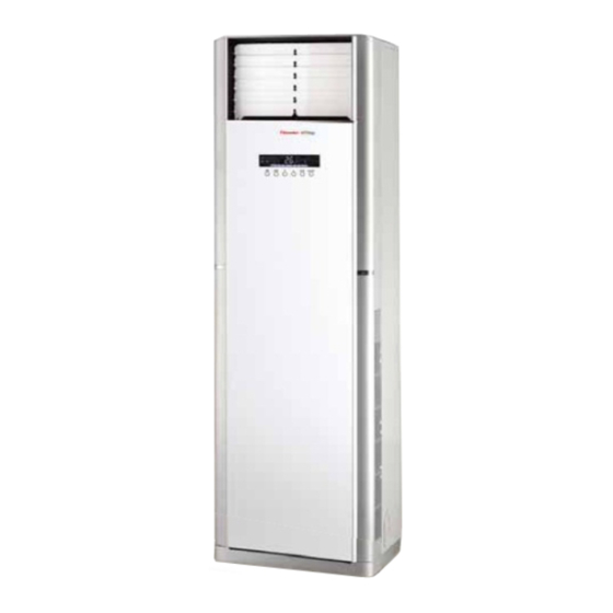
- Page 6 Part name Part name Indoor unit Air outlet Display Screen Display screen Air out and button Front panel Remote control window Wrapping Tape Air in FUN- MODE ON/OFF TION Outdoor unit Air in Connecting Pipe Drainage hose Air out Note: This photo is about the models of 24K, the appearance of model of 48K are a little different from this picture.
-
Page 7: Outline And Installation Dimensions Of Indoor Unit
Outline and installation dimension Outline and installation dimension Outline and installation dimensions of indoor unit Air in grill Rear view Outlet pipe opening Distance to ceiling Top view Distance to wall Distance to wall Unit:mm Dimension Applicable models Note:The distance from To barrier tubing side to the wall shall not be less than 30cm... -
Page 8: Outline And Installation Dimensions Of Outdoor Unit
Outline and installation dimensions of outdoor unit V1RF0-30 Unit:mm Bolt Wrench... - Page 9 V1RF0-50 Unit:mm Bolt Wrench...
-
Page 10: Electrical Circuit Diagram
5 5 5 5 5 Electrical circuit diagram Electrical circuit diagram V1RFI-30/V1RF0-30 These circuit diagrams are subject to change without notice, please refer to the one supplied with the unit. - Page 11 V1RFI-50/V1RF0-50 These circuit diagrams are subject to change without notice, please refer to the one supplied with the unit.
-
Page 12: Names And Functions Of Remote Control Buttons
Names and Functions of Remote Control Buttons Names and functions of remote control buttons Note: Be sure that there are no obstructions between receiver and remote control; Don't drop or throw the remote control; Don't let any liquid in the remote control and put the remote control directly under the sunlight or any place where is very hot. -
Page 13: Timer Button
Names and functions of remote control buttons NOTE: This Remote control is universal and it c o uld be used for many models of units. Some buttons are not availabl e to this unit will not be described below. TIMER AUTO Timer button HEALTH... - Page 14 Names and functions of remote control buttons NOTE: This Remote control is universal and it c o uld be used for many models of units. Some buttons are not availabl e to this unit will not be described below. BLOW Blow button Set Blow on (the characters of Blow will ●...
-
Page 15: Operation Of Remote Controller
Operation of Remote Controller Guide for operation-general operation 1.Press ON/OFF button to start the unit after powering the main unit on.(Note: Power the unit on every time, ON/OFF MODE the big -guide louver and small-guide louver will be closed firstly. 2.Press MODE button to select desired running mode. - Page 16 About AUTO RUN When AUTO RUN mode is selected, the setting temperature will not be displayed on the LCD, the unit will be in accordance with the room temp. automatically to select the suitable running method and to make ambient comfortable. About turbo function If start this function, the unit will run at super-high fan speed to cool or heat quickly so that the ambient temp.
-
Page 17: Changing Batteries And Notices
Changing Batteries and Notices Changing batteries notices 1.Slightly to press the place with along the arrowhead direction to push the back cover of remote controller. (As show in Fig 1. ) 2.Take out the old batteries, insert two AAA alkaline cells. -
Page 18: Explosive View And Spare Parts List
Explosive view and spare parts list Explosive view and spare parts list Exploded View of Components and Parts of Indoor unit V1RFI-30... - Page 19 Part Code Description V1RFI-30 01304126 Rear Plate Sub-Assy 01304130 Left Side Plate Sub-Assy 01304131 Right Side Plate Sub-Assy 22244089 Top Cover Sub-Assy 01364108D Breakwater Sub-Assy 12414072 Water Tray Sub-Assy 01004473 Evaporator Assy 390001375 Ambient Temperature Sensor 1521240302 Stepping Motor 15214002...
- Page 20 Exploded View of Components and Parts of outdoor unit V1RF0-30...
- Page 21 Part Code Description V1RFO-30 22415003 Front Grill 01435004P Cabinet 01305045P Front Side Plate 43005008 Electronic Expansion Valve 01205137P Chassis Sub-assy 46020006 Pressure Protect Switch 03025166 4-way Valve Assy 00105204 Compressor and fittings 01305044P Right Side Plate 01715012P Valve Support Sub-Assy 07133157 Cut-off Valve 26235001...
- Page 22 Exploded View of Components and Parts of Indoor unit V1RFI-50...
- Page 23 Part Code Description V1RFI-50 01304290 Rear Plate Assy 01304304 Left Side Plate Sub-Assy 01304303 Right Side Plate Sub-Assy 22244105 Top Cover Sub-Assy 01364154D Breakwater Sub-Assy 12414009 Water Tray Sub-Assy 01004178 Evaporator Assy 03004027 Capillary Sub-Assy 390001375 Ambient Temperature Sensor 06640112 Pipe Closure Sub-assy 1521240302 Stepping Motor...
- Page 24 Exploded View of Components and Parts of outdoor unit V1RFI-50...
- Page 25 Part Code Description V1RFO-50 22414102 Panel Grille 01435436 Cabinet 10338731 Axial Flow Fan 15013711 Fan Motor 01703095 Motor Support Sub-Assy 33010010 Capacitor CBB61 420111041 Terminal Board 33310274 Electrolytic Capacitor 01405669 Electric Box Assy 30030801 Filter Board 30039185 Main board 2 46010013 Fuse 44020345...
-
Page 26: 10 8 Trouble-Shooting
Trouble-Shooting Trouble-Shooting Universal Part Check insulation resistance for grounding; When set circuit breaker as Confirm if air-conditioning unit has ON , it trips immediately electrical leakage or is short-circuited Trip of circuit breaker or burn-out of fuse When turning the air-conditioning unit to the Check circuit breaker, measure ON status, trip of circuit breaker occurs resistance for short-circuit... - Page 27 Block in filter of indoor unit Periodically clean the filter Block in heat exchanger of outdoor unit Wash away dust on surface of heat exchanger Leakage between internal high pressure Replace compressor and low pressure sections of compressor Partial block in capillary Replace capillary Find out leakage position and charge Leakage of Refrigerant...
- Page 28 Block or breakage of drainage pipe Replace drainage pipe Water leakage The refrigerant pipe joint is not Wrap and bind it again firmly wrapped firmly Fan of indoor unit touches other Adjust fan position positions Foreign articles inside the indoor unit Remove foreign articles Adjust support foot mat or compressor, Vibration of compressor is violent...
- Page 29 Maintenance Guidelines Matters Need Attention Preparation before Repair Step 1: Confirm the unit model which needs repair and check the model and material code of the part which is easy to damage, especially the controller of outdoor unit. Step 2: Preliminarily determine the part which should be replaced according to malfunction description from the customer.
- Page 30 Common Malfunctions Analysis If malfunction or protection occurs to the unit, indoor unit will display relative code, so you can eliminate the malfunction according to the display. Display malfunction ------E4 is displayed on indoor unit Checking flowchart Discharge protection Check if outdoor unit is properlly installed. Poor ventilation will occur if air outlet is Adjust installation position blocked.
- Page 31 State 2: D101 LED on outdoor unit mainboard blinks 13 times Check if indoor unit and outdoor unit are Clean blocked by filth Insert the temp. sensor Check if discharge temp. sensor is properlly inserted properlly Replace electronic expansion Check if electronic expansion valve is normal valve Check if the cement resistances RES1 and Replace cement resistance...
- Page 32 State 2----- Abnormal power supply ( outdoor unit mainboard LEDs and power module LED are all black) Check if the voltage at power inlet (plugboard) Check power supply circuit of outdoor unit , AC-L1 and N1 of mainboard Normal input on outdoor unit AC 160-220V Check the voltage at two ends of mainboard...
- Page 33 Test the DC voltage between power modules P and N .If the voltage is 0, pull out the lines on P,N,U, V, W and test the resistance between P and N, Replace power TU and N, V and N, W and N.If any module value is approx.
- Page 34 Cut off the main power supply and then test the DC voltage between P and N of power module. If the value is 0, pull out the lines on P and N and test the resistance between P and N. If the value is approx. 0, the module may be damaged.
- Page 35 10. Door malfunction -------FC is displayed on indoor unit Checking method: The COM with silk print CN321 is for test of connection of door. When each COM is normal, the voltage is that if the door is completely closed: UP is 0V and DOWN IS 5V; if the door is in the middle: UP is 5V and DOWN is 5V;...
Need help?
Do you have a question about the V1RFI-30 and is the answer not in the manual?
Questions and answers