Table of Contents
Advertisement
Quick Links
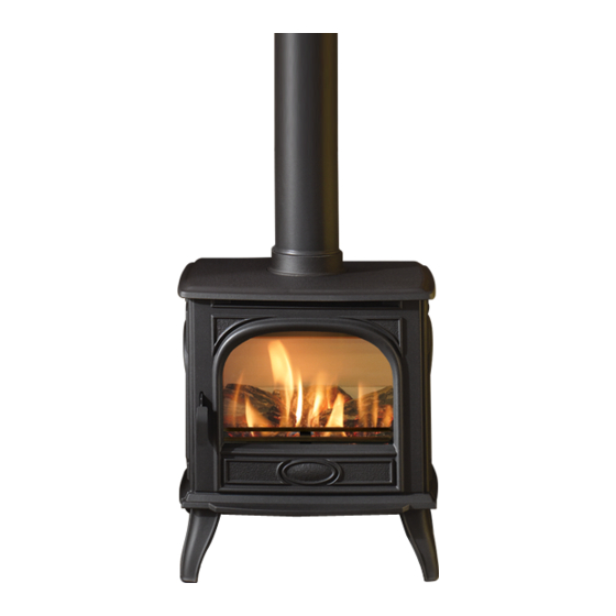
Conventional Flue Log Effect Stove
Instructions for Use, Installation and Servicing
For use in GB, IE (Great Britain and Republic of Ireland)
THE OUTER CASING, FRONT AND GLASS PANEL BECOME EXTREMELY HOT DURING OPERATION AND
WILL RESULT IN SERIOUS INJURY AND BURNS IF TOUCHED. IT IS THEREFORE RECOMMENDED THAT A
FIREGUARD COMPLYING WITH BS 8423:2002 IS USED IN THE PRESENCE OF YOUNG CHILDREN, THE
This product contains a Heat resistant glass panel. This panel should be checked during Installation and at each servicing interval. If any
damage is observed on the front face of the glass panel (scratches, scores, cracks or other surface defects), the glass panel must be
replaced and the appliance must not be used until a replacement is installed. Under no circumstances should the appliance be used if any
It is essential that ALL of the screws that retain the glass frame are replaced and tightened correctly. Under no circumstances should the
These Instructions must be left with the appliance for future reference and for consultation when servicing the appliance. Please make the
customer aware of the correct operation of the appliance before leaving these instructions with them.
The commissioning sheet found on Page 3 of this Instruction manual must be completed by the Installer prior to leaving the premises.
Dovre 280
With Upgradeable Control Valve
IMPORTANT
ELDERLY OR INFIRM.
damage is observed, the glass panel is removed or broken.
appliance be operated if any of these screws are loose or missing.
PR1812 Issue 2 (August 2014)
Advertisement
Table of Contents

Related Manuals for Dovre 280


Summary of Contents for Dovre 280
- Page 1 Dovre 280 Conventional Flue Log Effect Stove With Upgradeable Control Valve Instructions for Use, Installation and Servicing For use in GB, IE (Great Britain and Republic of Ireland) IMPORTANT THE OUTER CASING, FRONT AND GLASS PANEL BECOME EXTREMELY HOT DURING OPERATION AND WILL RESULT IN SERIOUS INJURY AND BURNS IF TOUCHED.
-
Page 2: Table Of Contents
Contents Covering the following models: Model NATURAL GAS Black DV541-010 DV541-409 Ivory DV541-042 DV541-440 Black Enamel DV541-093 DV541-456 Majolica Brown DV541-116 DV541-475 Appliance Commissioning Checklist ......3 User Instructions ............4 Installation Instructions ..........9 Technical Specifications ............. 9 Site Requirements ..............11 Installation ................ -
Page 3: Appliance Commissioning Checklist
Appliance Commissioning Checklist To assist us in any guarantee claim please complete the following information:- IMPORTANT NOTICE Explain the operation of the appliance to the end user, hand the completed instructions to them for safe keeping, as the information will be required when making any guaranteed claims. FLUE CHECK PASS FAIL... -
Page 4: User Instructions
Congratulations on purchasing your Dovre 280 stove, if No furnishings or other objects should be placed within installed correctly Dovre hope it will give you many years of 1 metre of the front of the appliance. warmth and pleasure for which it was designed. - Page 5 Dovre stockist. There is no requirement for this upgrade to be carried out by an approved Gas engineer. However Dovre recommend that this task is undertaken by a suitably competent person. This upgrade can be fitted before or after installation but if side clearances are limited then it will be easier to upgrade the appliance before installation.
- Page 6 User Instructions Remove the glass frame by undoing the fixing screws and 6. Arrangement of Fuel Bed lifting clear, see Diagram 4. Take care to support the glass window panel when removing the screws. Advice on handling and disposal Place carefully to one side. of fire ceramics The fuel effect of the log version of this appliance is made from Refractory Ceramic...
- Page 7 User Instructions Place the rear log into position between the rear brackets Once the logs are in there are two embers which can be and pushed up against the back panel, see Diagram 6. loosely placed at the front of the fuel bed and cover the tabs securing the burner tray, see Diagram 9.
- Page 8 10. Running In UNDER NO CIRCUMSTANCES SHOULD THE 10.1 During initial use of a new Dovre appliance a strong odour APPLIANCE BE USED IF ANY OF THE FRAME will be encountered as various surface coatings become hot RETAINING SCREWS ARE LOOSE OR MISSING.
-
Page 9: Installation Instructions
Pressure (Gross) High I 2H Natural (G20) 20mbar 6mm x 6mm 0.433 4.55 GB, IE Dovre 280 I 3P Propane (G31) 37mbar 1 x (14mm x 15mm) 0.164 4.35 GB, IE Efficiency Class 2 - 75% / NOx Class 4 Flue Outlet Size 127mm (5”) ø Gas Inlet Connection Size 8mm ø... - Page 10 This appliance has been certified for use in countries other than PACKING CHECKLIST those stated. To install this appliance in these countries, it is essential to obtain the translated instructions and in some cases the appliance will require modification. Contact Dovre for further Fixing Kit containing:- Qty Description information.
-
Page 11: Site Requirements
(10ft). Any horizontal flue run from the rear outlet must not exceed 100mm from the back of the appliance. The Dovre 280 has a nominal input not exceeding 7.0kW The chimney or flue must be free from any obstruction. Any... - Page 12 Installation Instructions Site Requirements MINIMUM CLEARANCE The appliance is not suitable for installation against a combustible wall. All combustible materials must be removed from behind the appliance. Ensure that all minimum clearances to combustible materials are complied with, see Diagrams 2 & 2A. The specified clearances provide the minimum distance to combustible materials.
-
Page 13: Installation
This remote control can control the gas appliance after the pilot has been lit. It can turn the main burner on and The appliance is fitted with the Dovre Flue Sure System, regulate it from low through to high and back again. - Page 14 Installation Instructions 3. Installation of the Appliance 5. Removing the Door Decide whether to use top or rear flue exit. IMPORTANT: THE OUTER PANELLING OF THE The appliance is factory built for rear flue exit but it can be APPLIANCE IS MADE FROM CAST IRON. USE changed to top exit by swapping the flue spigot and blanking CAUTION WHEN INSTALLING, REMOVING AND plate located on the appliance.
- Page 15 Installation Instructions Place the rear log into position between the rear brackets 6. Arrangement of Fuel Bed and pushed up against the back panel, see Diagram 6. Advice on handling and disposal of fire ceramics The fuel effect of the log version of this appliance is made from Refractory Ceramic Fibre (RCF), a material which is commonly used for this application.
- Page 16 Installation Instructions Once the logs are in there are two embers which can be 8. Completion of Assembly loosely placed at the front of the fuel bed and cover the tabs securing the burner tray, see Diagram 9. Use a ceramic glass product generally sold for cleaning ceramic hobs to clean the glass front.
- Page 17 Installation Instructions 8. Operating the Appliance The control valve is at the foot on the right-hand side of the appliance. It has two controls, see Diagram 15: 1. The right-hand knob controls the pilot ignition 2. The left-hand knob controls the main burner Refer to separate instructions if your appliance is upgraded to include battery remote control.
-
Page 18: Commissioning
Commissioning 1. Commissioning Close all doors and windows in the room. Ignite the appliance and operate on maximum for 10 minutes. Position a lighted smoke match just inside the draught diverter opening at the rear of the appliance. Check all smoke is drawn into the opening, see Diagram 1. Rear of Appliance Draft diverter lip Smoke match... -
Page 19: Servicing Requirements
Re-commission the appliance in accordance with purchased via the retailer from which the appliance was Commissioning Procedures. purchased or any other Dovre distributor. Advise the customer of any remedial work undertaken. This appliance must be serviced at least once a year by a competent person. - Page 20 Servicing Instructions Fault Finding Charts...
-
Page 21: How To Replace Parts
Servicing Instructions - Replacing Parts 1. General 3. Window Frame Assembly All main components can be replaced without removing the Remove the glass frame by undoing the fixing screws and appliance from its installation. lifting clear, see Diagram 3. Take care to support the glass window panel when removing the screws. - Page 22 Servicing Instructions - Replacing Parts 4. Baffle & Ceramic Liners To access the burner tray and interior workings of the appliance it may be necessary to remove the baffle and the liners. BAFFLE The baffle must be removed before the liners can be taken out of the appliance.
- Page 23 Servicing Instructions - Replacing Parts 5. Main Burner 6a Pilot Burner Bracket Remove the two fixing screws from the pilot bracket, see To replace the main burner: Diagram 11. Gently draw the assemble away from the firebox to give access to the nuts and ignition lead. Remove the baffle and enamel liners, see Section 4.
- Page 24 Servicing Instructions - Replacing Parts 6d Thermocouple Undo the retaining nut and withdraw the thermocouple. Undo the thermocouple from the back of the gas valve, see Diagram 14. Reassemble in reverse order. Do not overtighten. Disconnect the other end of the ignition lead from the valve body noting the route of the ignition lead.
- Page 25 Servicing Instructions - Replacing Parts 11.6 Holding the injector with a spanner: 10. Magnetic Safety Valve Undo the feed pipe. Note the orientation of the Injector. 11.7 10.1 Turn the gas supply off at the isolation device. 11.8 Re-assemble in reverse order. 10.2 Undo the thermocouple connection from the back of the gas 11.9...
-
Page 26: Basic Spare Parts List
Servicing Instructions - Replacing Parts 12.6 Refit the new sensor ensuring the plastic spacers are 14. Changing Between Gas Types located between the bracket and the sensor. 12.7 Refit the leads. In order to change between gas types, it will be necessary to change the following items: 12.8 Feed the cable back through the hole as you replace the... -
Page 27: Service Records
Service Records 1ST SERVICE 2ND SERVICE Date of Service ................. Date of Service ............... Next Service Due ..............Next Service Due ..............Signed ..................Signed ..................Retailer's Stamp/Gas Safe Registration Number Retailer's Stamp/Gas Safe Registration Number 3RD SERVICE 4TH SERVICE Date of Service ................. Date of Service ............... - Page 28 E & O E...
Need help?
Do you have a question about the 280 and is the answer not in the manual?
Questions and answers