
Related Manuals for Hammer Strength Heavy Duty Power Rack


Summary of Contents for Hammer Strength Heavy Duty Power Rack
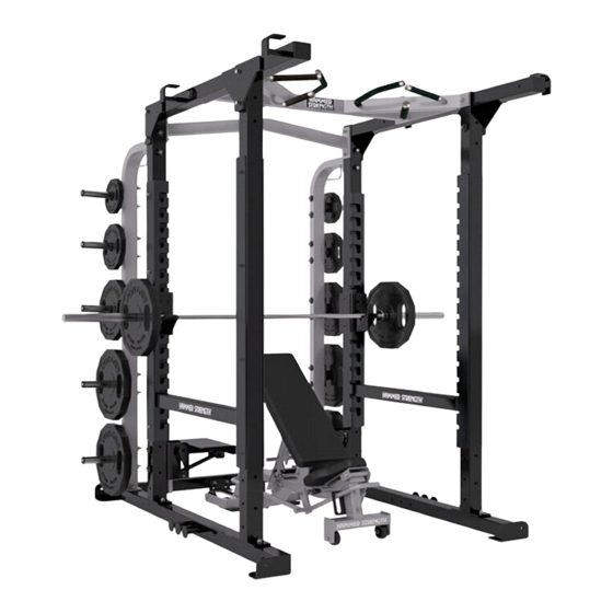
- Page 1 HEAVY DUTY POWER RACK (HDPR) WARNING: Read and follow all directions for each step to insure proper assembly of this product. CLASS SB (Studio): Professional and / or commercial use (Commercial Use Only) PART #76715401 D-1 DATE: 2/08...
- Page 2 HAMMER STRENGTH HEAVY DUTY RACKS Purchasers of Hammer Strength products should read the Owner's Manual and all of the warning labels on the products before using them. Because these products may be used in commercial settings, it is the purchaser's responsibility to instruct all individuals, whether users, trainers or observers, on the proper usage of the equipment.
- Page 3 MODEL SERIAL # MFG. & DESIGN BY GARY JONES & THE TROOPS MACHINE WARRANTY VOID IF TAG REMOVED For Service Call Life Fitness 800-351-3737 WARNING SERIOUS INJURY CAN OCCUR ON THIS EQUIPMENT. YOU MUST FOLLOW THESE PRECAUTIONS TO AVOID INJURY! 1.
- Page 4 Insure the Product, and Include a letter explaining the defect or problem and a copy of your proof of purchase if you believe the service is covered by warranty Life Fitness World Headquarters Attn: CSS Help Desk 5100 N. River Rd.
- Page 5 3. Bolts: Most hardware is English and has a corrosion resistant finish. Grade 5 or greater in strength. 4. Equipment Anchoring: All machines have holes in the feet, these allow easy anchoring to the floor. Life Fitness rec- ommends that all machines be anchored to the floor to minimize the possibility of tipping.
-
Page 6: Components List
COMPONENTS LIST * ITEM NO. QTY. Refer to the HDPR8 and HDPR9 Parts List to identify part numbers for orders. ANG-WT-HORN-ASSY REQUIRED TOOLS *3/4” WRENCH *9/16” WRENCH *RATCHET with 9/16” SOCKET *RATCHET with 3/4” SOCKET *7/32” ALLEN WRENCH * Contact Customer Service at (800) 351-3737 or (847) 451-0036 for a detailed parts list. PART NO. - Page 7 ½” Internal Lock Washer ½” Lock Nut HARDWARE: ½ X 3-1/2” Bolt ½ X 4-1/2” Bolt 3/8 X 4-1/2” Bolt 3/8” Flat Washer 3/8” Lock Nut Backing Dome Washer Backing Dome Washer...
- Page 8 STEP 1: LOOSELY assemble both FRONT LEFT UPRIGHTS (1) to the LOWER LEFT BASE (2) using four 1/2 X 4-1/2” BOLTS (3), four BACKING DOME WASHERS (4), four 1/2” INT LOCK WASHERS (5), and four 1/2” LOCK NUTS (6). LOOSELY assemble both FRONT RIGHT UPRIGHTS (7) to the LOWER RIGHT BASE (8) using four 1/2 X 4-1/2” BOLTS (3), four BACKING DOME WASHERS (4), four 1/2”...
- Page 9 STEP 2: LOOSELY assemble the REAR CROSS BRACE (9) to the bottom of the LOWER LEFT BASE (2) and LOWER RIGHT BASE (8) using four 1/2 X 4-1/2” BOLTS (3), four BACKING DOME WASHERS (4), four 1/2” INT TOOTH LOCK WASHERS (5) and four 1/2” LOCK NUTS (6).
- Page 10 STEP 3: LOOSELY assemble the TOP CROSS BEAM (10) and UPPER LEFT and RIGHT SIDE FRAMES (11 & 12) to the FRONT LEFT and RIGHT UPRIGHTS (1 & 7) using six 1/2 X 4-1/2” BOLTS (3), ten 1/2” INT LOCK WASHERS (5), two BACKING DOME WASHERS (4) and six 1/2”...
- Page 11 STEP 4: LOOSELY assemble the PULL-UP BAR (13) to the UPPER LEFT & RIGHT SIDE FRAMES (11 & 12) using two 1/2 X 4-1/2” BOLTS (3), two BACKING DOME WASHERS (4), two 1/2” INT LOCK WASHERS (5), and two 1/2” LOCK NUTS (6).
- Page 12 STEP 5: LOOSELY assemble the two REAR UPRIGHTS (14) to the LOWER LEFT & RIGHT BASES (2 & 8) and FRONT LEFT & RIGHT UPRIGHTS (1 & 7) using eight 1/2 x 4-1/2” BOLTS (3), eight 1/2” BACKING DOME WASHERS (4), eight 1/2”...
- Page 13 17 18 STEP 6: SECURELY assemble the bottom of the ten WEIGHT HORNS (15) to the REAR UPRIGHTS (14) using ten 3/8 x 4- 1/2” BOLTS (16), ten BACKING DOME WASHERS (4), twenty 3/8” FLAT WASHERS (17), and ten 3/8” LOCK NUTS (18).
- Page 14 STEP 7: Assemble the SHORT BENCH LOCK (19) to the REAR CROSS BRACE (9) using two 1/2 X 3-1/2” BOLTS (20), two BACKING DOME WASHERS (4), two 1/2” INT LOCK WASHERS (5), and two 1/2” LOCK NUTS (6). Insert the LEFT BAR SUPPORT (21) into the desired slots of the FRONT LEFT UPRIGHT (1), and allow it to drop down to lock in place.
- Page 15 STEP 8: Spotter Platform accessories are available for the HDPR8. Assemble each Spotter Platform (C) to the FRONT LEFT & RIGHT UPRIGHTS (1 & 7) using two BOLTS (D), two DOME WASHERS (E), two SPACERS (F), one WEAR PLATE (G), two FLAT WASHERS (H), and two NUTS (I) as shown in the illustration.
- Page 16 Action Daily Clean Hand Grips Inspect Visual Overall X Hardware Frame Hand Grips Clean: • Hand grips with mild soap and water. • Frame damage can be repaired with touch-up paint can be purchased from your Hammer Strength customer service representative. Inspect: •...
Need help?
Do you have a question about the Heavy Duty Power Rack and is the answer not in the manual?
Questions and answers