JRC JSS-2150 Instruction Manual
150w mf/hf radio equipment
Hide thumbs
Also See for JSS-2150:
- Instruction manual (248 pages) ,
- Installation manual (114 pages) ,
- Brochure (6 pages)

Related Manuals for JRC JSS-2150


Summary of Contents for JRC JSS-2150
- Page 1 JSS - 2150 2150 150W MF/HF RADIO EQUIPMENT 150W MF/HF RADIO EQUIPMENT INSTRUCTION INSTRUCTION MANUAL MANUAL...
- Page 3 CAUTIONS AGAINST HIGH VOLTAGE Radio and radar devices are operated by high voltages of anywhere from a few hundred volts up to many hundreds of thousands of volts. Although there is no danger with normal use, it is very dangerous if contact is made with the internal parts of these devices. (Only specialists should attempt any maintenance, checking or adjusting.) There is a very high risk of death by even a few thousand volts, in some cases you can be fatally electrocuted by just a few hundred volts.
- Page 4 First aid ☆Note points for first aid Unless there is impending danger leave the victim where he or she is, then begin artificial respiration. Once you begin artificial respiration, you must continue without losing rhythm. (1) Make contact with the victim cautiously, there is a risk that you may get electrocuted. (2) Switch off the machinery and then move the victim away slowly if you must.
- Page 5 ☆If the victim has a pulse but is not breathing (“Mouth to mouth” resuscitation) Figure 1 (1) Place the victim’s head facing backward (place something under the neck like a pillow). (2) Point the chin upward to widen the trachea. (3) Pinch the victim’s nose, take a deep breath, then put your mouth over the victim’s mouth and exhale completely, making sure that your mouth completely covers the victim’s mouth.
- Page 6 ☆ If the victim has no pulse and is not breathing (Heart massage in combination with artificial respiration.) Figure 2 If the victim has no pulse, his or her pupils are dilated, and if you cannot detect a heartbeat, the heart may have stopped, beginning artificial respiration is critical.
- Page 7 Preface Thank you for choosing the Model JRC JSS-2150 150W MF/HF radio equipment. This radio equipment can be used as a Global Maritime Distress and Safety System (GMDSS) radio device, compliant with international regulations, that provides emergency communications and standard communications capabilities for small and large ships.
-
Page 8: Before Operation
Before operation Concerning the symbols This manual uses the following symbols to explain correct operation and to prevent injury or damage to property. The symbols and descriptions are as follows. Understand them before proceeding with this manual. WARNING Indicates a warning that, if ignored, may result in serious injury or even death. -
Page 9: Handling Precautions
Doing so may save the lives of the crews and passengers on the ship in distress. This equipment is used for both distress communication and routine communication. Contact JRC or our agent if any problem is observed in this unit during routine operation or inspection. - Page 10 Handling precautions CAUTION Do not use this equipment anyplace other than specified. Doing so may cause failure or malfunction. Do not turn the trimmer resistors or the trimmer capacitors on the PCB unit. Doing so may cause failure or malfunction. Do not install the equipment in a place near water or in one with excessive humidity, steam, dust, or soot.
- Page 11 CAUTION When sending a drobose call, do not press the DISTRESS key. Doing so may cause a false distress call. (Drobose calls can be sent via the [Call] button displayed on the screen.) A distress acknowledgement or a distress relay call can be transmitted from a received distress message stored in the log, but when sending such a call, follow the instructions of the ship's captain or officer in charge.
-
Page 12: Distress Calls
Sending a Distress Call (Distress Alert) CAUTION When sending a distress call, follow the instructions of the ship's captain or officer in charge. Open the DISTRESS key cover on the NCM-2150 controller. Press and hold the DISTRESS key for 4 seconds to send the distress call. When the countdown is finished the screen below on the right is displayed, and after tuning the antenna to the frequency, the distress call is transmitted. - Page 13 After receiving acknowledgement, use the radiotelephone to request rescue. First, the responding station calls by radiotelephone. Communicate the following information to that station. Say "MAYDAY". Say "This is (name of your ship)". Tell the station the ship's Maritime Mobile Service Identity (MMSI) number, call sign, ship's position, nature of distress, and rescue requests.
-
Page 14: Receiving A Distress Call
Receiving a Distress Call WARNING If a distress call is received, make sure to inform the ship's captain or officer in charge. Doing so may save the lives of the crew and passengers on the ship in distress. When a distress call is received, the distress message is displayed. The ALM lamp starts blinking, and an alarm gradually grows louder. -
Page 15: Equipment Exterior
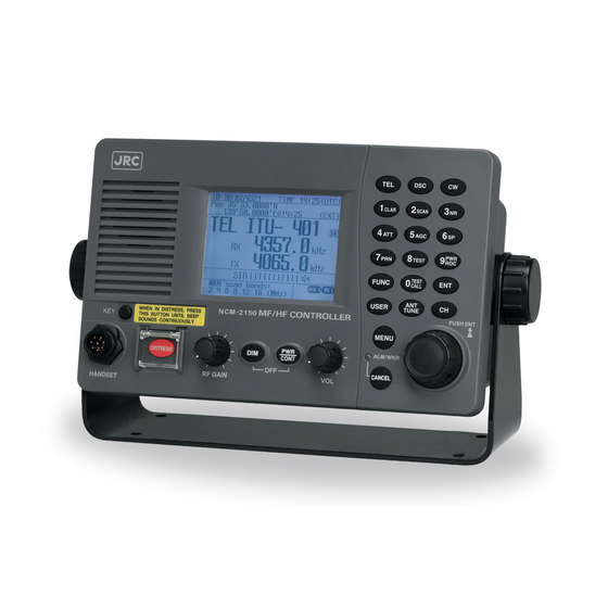
Equipment exterior ● JSS-2150 150W MF/HF Radio Equipment NTD-2150 150 W MF/HF Transceiver NFC-2150 Antenna Tuner NCM-2150 MF/HF Controller/NQW-261 Handset xiii... - Page 16 NKG-91 Printer DPU-414 Printer ● ● NKG-800 Printer NBD-2150 AC/DC Power supply ● ● NBB-724 Battery charger NCH-321A Distress Message Controller (DMC) ● ●...
-
Page 17: Table Of Contents
Contents Preface ......................Before operation ..................Handling precautions ................. DISTRESS CALLS ..................Equipment exterior ..................xiii Glossary of terms ..................1. EQUIPMENT OVERVIEW ................ Functions ........................Features ........................Basic configuration ....................1.3.1 Basic configuration of the main unit ..............1.3.2 Options ......................... - Page 18 Setting the radio ......................4-10 4.3.1 Setting the communication frequencies .............. 4-10 4.3.2 Setting the communication channels ..............4-11 4.3.3 Setting the automatic gain control (AGC) ............4-15 4.3.4 Setting the noise reduction (NR) ................. 4-15 4.3.5 Setting the attenuation (ATT) ................
- Page 19 6-12 6.5.5 Regular replacement parts ................... 6-12 7. AFTER-SALES SERVICE ................ 8. DISPOSAL ....................9. SPECIFICATIONS ..................JSS-2150 150W MF/HF Radio Equipment ..............Options ........................Peripheral interfaces ....................10. OPTIONS OPERATION ................. 10-1 10.1 AC/DC power supply (NBD-2150) ................10-1 10.2 Battery charger (NBB-724)
- Page 20 11. Appendix ....................11-1 11.1 Frequencies for distress and safety calls ..............11-1 11.2 National DSC frequencies for routine calls ............... 11-2 11.3 International DSC frequencies for routine calls ............11-2 11.4 ITU channel list (TEL/CW) ..................11-3 11.5 Guide to MF/HF operation ..................
-
Page 21: Glossary Of Terms
Glossary of terms This section defines general and DSC terms related to this equipment. ● General terms Digital Selective Calling device Remote Maintenance System Used in routine calls, safety and urgency Transmits ship equipment information calls, and distress calls for rescue requests. temporarily stored in the VDR via Inmarsat to land, maintenance... - Page 22 ● DSC terms Address Polling General term for Maritime Mobile Serive Polling is a feature for routine calling. Identity number (MMSI). It is used, for example, to confirm whether a This equipment uses To/From to distinguish ship is within radio range when a coast between the sender and receiver.
- Page 23 Type Intent Message code indicating the type of the call. Message code indicating specific content. Codes are listed below. Indicates the type of the call for a specific ・ Individual call… Individual call message purpose, not for radiotelephone ・ Individual ACK… Acknowledgement communication.
- Page 24 xxii...
-
Page 25: Equipment Overview
Equipment Overview 1. EQUIPMENT OVERVIEW 1.1 Functions This equipment includes MF/HF transceiver, Class-A DSC and DSC watch keeping receiver required as the Global Maritime Distress and Safety System (GMDSS). It is designed as a separated transceiver and small, lightweight controller(s) for easy installation not only in international passenger ships and freight ships of 300 tons or more, but also conventional ships of less than 300 tons. -
Page 26: Basic Configuration
Equipment Overview 1.3 Basic configuration 1.3.1 Basic configuration of the main unit Description Model Notes MF/HF transceiver NTD-2150 Includes the connection cable MF/HF controller NCM-2150 (7ZCJD0343) Handset NQW-261 Includes the cradle Antenna tuner NFC-2150 Instruction manual 7ZPJD0449 This manual 1.3.2 Options Description Model... -
Page 27: System Configuration
Equipment Overview 1.3.3 System configuration NKG-91 Printer NCM-2150 MF/HF Controller Expansion Controller NFC-2150 Antenna Tuner NTD-2150 MF/HF Transceiver NCH-321A DMC * The equipment can also be connected to the VDR server to use the remote maintenance system. NBD-2150 AC/DC Power Supply NBB-724 Battery Charger... -
Page 28: External Dimensions
Equipment Overview 1.4 External dimensions Below are the external dimensions of each unit. MF/HF Transceiver (NTD-2150) (1) Unit: mm Weight: Approx. 13 kg MF/HF Controller (NCM-2150) (2) Unit: mm Weight: Approx. 1.3 kg... - Page 29 Equipment Overview Handset (NQW-261) (3) . Unit: mm Mounting hole Weight: Approx. 0.5 kg Connection box (NQD-2250) (4) Unit: mm Weight: Approx. 0.6 kg...
- Page 30 Equipment Overview Antenna Tuner (NFC-2150) (5) Unit: mm Weight: Approx. 3.3 kg Junction Box (NQD-2253) (6) Unit: mm Weight: Approx. 1.2 kg...
- Page 31 Equipment Overview AC/DC Power Supply (NBD-2150) (7) Unit: mm Weight: Approx. 9.8 kg...
- Page 32 Equipment Overview Battery Charger (NBB-724) (8) Unit: mm Weight: Approx. 12.0 kg...
- Page 33 Equipment Overview Printer (NKG-91) (9) ● Wall mount type Wiring hole (side) Mounting hole Unit: mm Wiring hole (back) Weight: Approx. 1.5 kg ● Flush mount type Unit: mm Weight: Approx. 0.8 kg...
- Page 34 Equipment Overview (10) Printer (DPU-414) ● Desktop type Unit: mm Weight: Approx. 0.6 kg 1-10...
- Page 35 Equipment Overview (11) Printer (NKG-800) ● Desktop type Unit: mm Weight: Approx. 3.7 kg 1-11...
-
Page 36: Block Diagram
Equipment Overview 1.5 Block diagram Rx/WKR antenna Tx antenna JQD-69C Joint box Lead wire RG-12/UY TH-7/1.6 M-P-7 M-P-7 RX/WKR ANT TX ANT M-P-7 M-A-JJ TTYCS- 4 RG-10/UY 5D-2VH NQD-2250 DPYC-2.5(x2) NTD-2150 Connection box NFC-2150 MF/HF Transceiver Antenna tuner TTYCS-4 7ZCJD0343 NQD-2253 NQW-261 (5m)... -
Page 37: Names And Functions
Names and Functions 2. NAMES AND FUNCTIONS 2.1 Controller (NCM-2150) The controller parts and their functions are described below. 10 11 1. Internal loud speaker 2. Jack for telegraph in continuous wave (CW) mode 3. Numeric keypad (10-key) and function keys In addition to entering numeric values, when combined with the FUNC key, the keys have the following functions. - Page 38 Names and Functions ・ ····· Enter key. USER ····· User defined key. Register a frequently used menu and use this key to open it ・ quickly. ····· Tunes the antenna. ・ TUNE ····· Sets the communication channel input mode (user channel, ITU channel, or free ・...
-
Page 39: Main Displays
Names and Functions 2.2 Main displays The LCD screen on the controller changes according to current conditions. This section describes the status display, FUNC menu, main menu, and DSC message receiving screens. 2.2.1 Status display I D 4 3 1 0 0 1 2 3 4 T I M E 2 3 : 5 9 ( U T C ) P o s 8 9 ゚... -
Page 40: Function Screen And Key Operations
Names and Functions 2.2.2 Function screen and key operations The functions assigned to the number keys are temporarily enabled by pressing the FUNC key in the status display or pressing and holding the FUNC key and then pressing the number key. : Displays the clarifier adjustment menu CLAR Indicates the enabled number key and its... -
Page 41: Menu Screen
Names and Functions 2.2.3 Menu screen I D 4 3 1 0 0 1 2 3 4 T I M E 2 3 : 5 9 ( U T C ) P o s 8 9 ゚ 5 9 . 0 1 2 3 ' N 1 7 9 ゚... -
Page 42: Installation
Installation 3. INSTALLATION CAUTION To install this equipment, contact our service center or agents. Special knowledge on selecting the place where the antenna is to be mounted and setting the ID number (MMSI) assigned to the ship is required in addition to installing the equipment. -
Page 43: Operation
Operation 4. OPERATION This chapter describes basic controller operations, radiotelephone communications, DSC calling procedures, and other radio functions. Controller operation overview Basically, the controller is operated with the numeric keypad (10key), the MENU key, and jog dial. The following is an overview of their operation. When two controllers are connected, only one controller having the access right can operate the radiotelephone, except for sending a distress call, changing audio volume, and changing display conditions. -
Page 44: Menu Tree
Operation Menu tree Main Menu Hierarchical Menu 1 Hierarchical Menu 2 Shortcut Key Note 1. DSC non-distress call FUNC - 0 2. DSC drobose call 3. Editing a distress msg 4. DSC logs 4.1 Received distress (Received message screen) Printable 4.2 Received others (Received message screen) Printable... -
Page 45: Basic Communications Procedure
When two controllers are connected, and one controller is turned on from sleep mode, the status display is displayed immediately without checking operations. If errors are detected during the operation check, the message is displayed. Please inform JRC or our agent of the error contents. -
Page 46: Turning Off The Power/ Putting Into Sleep Mode
Operation 4.2.2 Turning off the power/ Putting into sleep mode CAUTION When completely turning off the power to the equipment, turn off the breaker on the transceiver ■ ■ Procedure PW R Press the key and C O N T simultaneously. -
Page 47: Communicating In Radiotelephone Mode
Operation 4.2.3 Communicating in radiotelephone mode Use the handset to communicate in radiotelephone mode. ■ ■ Procedure When operating on a controller without access rights (OCC is displayed), press the jog dial to obtain the access rights. Unless the controller with access rights is being used, the access rights are acquired and the OCC display on the screen disappears. - Page 48 Operation A N T Press the key to tune the antenna. T U N E TUNE blinks if the transmission Note frequency is not tuned. Even if TUNE is not displayed, tune the antenna before making a call. TUNE lights during tuning. It goes out after tuning.
- Page 49 Operation 4.2.4 Communicating in CW mode Use a CW keyer to communicate in CW mode. ■ ■ Procedure When operating on a controller without access rights (OCC is displayed), press the jog dial to obtain the access rights. Unless the controller with access rights is being used, the access rights are acquired and the OCC display on the screen disappears.
- Page 50 Operation Press the A N T key to tune the antenna. T U N E TUNE blinks if the transmission Note frequency is not tuned. Even if TUNE is not displayed, tune the antenna before making a call. TUNE lights during tuning. It goes out after tuning.
-
Page 51: Receiving Am Broadcasts
Operation 4.2.5 Receiving AM broadcasts It is possible to listen to the radio in AM mode. ■ ■ Procedure When operating on a controller without access rights (OCC is displayed), press the jog dial to obtain the access rights. Unless the controller with access rights is being used, the access rights are acquired and the OCC display on the screen disappears. -
Page 52: Setting The Radio
Operation 4.3 Setting the radio This section describes how to set the communication frequencies and how to use the receiver and transceiver functions. 4.3.1 Setting the communication frequencies Use the free frequency input mode to input the communication frequencies directly. ■... -
Page 53: Setting The Communication Channels
Operation 4.3.2 Setting the communication channels Besides the free frequencies described previously, ITU channel mode and user channel modes can also be set. The ITU channel mode is mode for using channels based on the international standard and is built-in to the equipment. The user channel mode is the mode for using channels on pre-registered frequencies. - Page 54 Operation (2) Setting the ITU channels ■ ■ Procedure After setting the TEL or CW communication modes, pressing the key opens the status display for the ITU channel mode. I D 4 3 1 0 0 1 2 3 4 T I M E 2 3 : 5 9 ( U T C ) Input the channel by using the numeric P o s 8 9 ゚...
- Page 55 Operation (3) Setting user channels A total of 20 groups with 20 channels set to each group (i.e. 400 channels) can be registered on the equipment. This section explains how to set channels that are already registered. ■ ■ Procedure Use the key to open the user channel I D 4 3 1 0 0 1 2 3 4...
- Page 56 Select 1. User channel list and press ENT. 5.1)User channel list (index) No CH group name Type 01 JRC Tokyo The user channel list index (group list) as Pacific ABC shown at right is displayed. Select the intended channel group and press 5.1)User channel list (table)
-
Page 57: Setting The Automatic Gain Control (Agc)
Operation 4.3.3 Setting the automatic gain control (AGC) ■ ■ Procedure Press the key, and through MENU 5.4)Receiver hierarchical menus, select 5.4 Receiver. 1.Auto gain control :Slow 2.Noise reduction :OFF 3.Attenuation :OFF 4.Clarifier :+000Hz 5.Squelch :OFF 6.CW bandwidth :Narrow 7.Scan 0.Back Select 1. -
Page 58: Setting The Attenuation (Att)
Operation 4.3.5 Setting the attenuation (ATT) ■ ■ Procedure Press the key, and through MENU 5.4)Receiver hierarchical menus, after 5.4 Receiver 1.Auto gain control :Slow 2.Noise reduction :OFF appears, move the cursor to 3. 3.Attenuation :OFF 4.Clarifier :+000Hz Attenuation. 5.Squelch :OFF 6.CW bandwidth :Narrow... -
Page 59: Setting The Squelch Level
Operation 4.3.7 Setting the squelch level ■ ■ Procedure Press the key, and through MENU 5.4)Receiver hierarchical menus, after 5.4 Receiver 1.Auto gain control :Slow 2.Noise reduction :OFF appears, move the cursor to 5. Squelch. 3.Attenuation :OFF 4.Clarifier :+000Hz 5.Squelch :OFF 6.CW bandwidth :Narrow... -
Page 60: Scanning The Rx Frequencies
7.Scan 0.Back Press ENT to confirm the selection. 5.4.7)Scan No CH group name Type 01 JRC Tokyo The group list as shown at right is displayed. Pacific ABC The previous scan can be restarted Note by pressing and holding the... -
Page 61: Reducing The Tx Power
Operation 4.3.10 Reducing the Tx power ■ ■ Procedure Press the key, and through MENU 5.5)Transmitter hierarchical menus, select 5.5 1.Power :High 2.Tune power :Normal Transmitter. 0.Back 1. Select Power and press ENT to move 5.5)Transmitter the cursor to the right, then use the jog dial 1.Power :Low 2.Tune power... -
Page 62: Basic Dsc Operations
Operation 4.4 Basic DSC operations When calling stations, the DSC is also available for a routine, safety, urgency, or a distress call. This section explains basics of how to use the DSC to make routine calls. 4.4.1 Routine calls to an individual station For radiotelephone communication, a DSC routine call to an objective station can be made as follows. - Page 63 Operation When input is complete, the cursor 1)DSC non-distress call moves to Call. Call type :[RTN/Indv/TEL Address :[431123456] Calling FRQ:[Tx 2169.0kHz] Check the settings before making routine :[Rx 2169.0kHz] Working FRQ:[Tx 2065.0kHz] calls. 2065.0kHz] Select Preview and press ENT before Note [Call] [Preview]...
- Page 64 Operation I D 4 3 1 0 0 1 2 3 4 T I M E 0 0 : 0 0 ( U T C ) Press the CANCEL key or ENT. P o s 8 9 ゚ 5 9 . 0 1 2 3 ' N 1 7 9 ゚...
-
Page 65: Routine Calls To A Group Of Ships
Operation 4.4.2 Routine calls to a group of ships For radiotelephone broadcasting, a DSC routine call to a group of ships can be made as follows. ■ ■ Procedure Press key, and through MENU 1)DSC non-distress call Call type :[RTN/Indv/TEL hierarchical menus, select 1. - Page 66 Operation When input is complete, the cursor 1)DSC non-distress call Call type :[RTN/Group/TEL ] moves to Call. Address :[043123456] Calling FRQ:[Tx 2169.0kHz] :[Rx 2169.0kHz] Check the settings before making routine Working FRQ:[Tx 2065.0kHz] calls. Select Preview and press ENT before Note [Call] [Preview]...
-
Page 67: Receiving Routine Calls
Operation 4.4.3 Receiving routine calls When receiving a DSC call from a coast or ship station, the message will be displayed immediately on the screen. After that, perform the following procedures as appropriate. (1) Receiving an individual call (type: radiotelephone) ■... - Page 68 Operation I D 4 3 1 0 0 1 2 3 4 T I M E 2 3 : 5 9 ( U T C ) After sending an acknowledgement P o s 8 9 ゚ 5 9 . 0 1 2 3 ' N 1 7 9 ゚...
- Page 69 Operation (2) Receiving an individual call (type: polling) ■ ■ Procedure The screen at right is displayed, and the ALM lamp blinks and the alarm grows louder gradually. The example message contains the following information. Message type: Individual call Caller's MMSI: 001234567 Purpose of call: Polling...
- Page 70 Operation (3) Receiving a group call ■ ■ Procedure The screen at right is displayed, and the ALM lamp blinks and the alarm grows louder gradually. The example message contains the following information. Message type: Group call Caller's MMSI: 123456789 Communication mode: Radiotelephone Work frequency: Receiving 2065.0 kHz...
-
Page 71: Emergency Calls (Dsc Safety/Urgency/Distress Calls)
Operation 4.5 Emergency calls (DSC safety/urgency/distress calls) In emergency, the DSC is available for safety, urgency, or distress calls. For safety and urgency calls, either individual calls or area calls is selectable for the type of call. For distress calls, enabled to send either after entering the nature of distress or frequency, or without entering anything. - Page 72 Operation To change the call frequency, select Calling FRQ and press ENT to move the 1)DSC non-distress call Call type :[SAF/Indv/TEL cursor to the right. Then select the Address :[431123456] Calling FRQ:[ 4207.5kHz] distress and safety frequencies using the Working FRQ:[ 2182.0kHz] jog dial.
- Page 73 Operation Area calls For radiotelephone broadcasting, a DSC safety area call can be made as follows. ■ ■ Procedure Press key, and through MENU 1)DSC non-distress call hierarchical menus, select 1. DSC Call type :[RTN/Indv/TEL Address non-distress call. Calling FRQ:[Tx 2177.0kHz] :[Rx 2177.0kHz]...
- Page 74 Operation Press ENT. 1)DSC non-distress call Call type :[SAF/Area/TEL Area form :[Center&rad] The work frequency of the same band as the - Center :[89゚N179゚E] input Calling FRQ is automatically set in - Radius :[0500NM] Calling FRQ:[ 4207.5kHz] Working FRQ and the cursor moves to Working FRQ:[ 4125.0kHz] Working FRQ.
- Page 75 Operation Other features of safety calls (position request/test) Use safety calls to request position information to stations and to make DSC test calls. (1) Position request call ■ ■ Procedure Press key, and through MENU 1)DSC non-distress call Call type :[RTN/Indv/TEL hierarchical menus, select 1.
- Page 76 Operation I D 4 3 1 0 0 1 2 3 4 T I M E 2 3 : 5 9 ( U T C ) Select Call and press ENT to start the P o s 8 9 ゚ 5 9 . 0 1 2 3 ' N 1 7 9 ゚...
- Page 77 Operation (2) Test call ■ ■ Procedure Press key, and through MENU 1)DSC non-distress call Call type :[RTN/Indv/TEL hierarchical menus, select 1. DSC Address Calling FRQ:[Tx 2177.0kHz] non-distress call. :[Rx 2177.0kHz] Working FRQ:[Tx . kHz] . kHz] [Call] [Preview] [Cancel] Select Call type and press ENT to move 1)DSC non-distress call Call type...
- Page 78 Operation I D 4 3 1 0 0 1 2 3 4 T I M E 2 3 : 5 9 ( U T C ) Select Call and press ENT to start the P o s 8 9 ゚ 5 9 . 0 1 2 3 ' N 1 7 9 ゚...
-
Page 79: Receiving Safety Calls
Operation Receiving safety calls When receiving a safety call from a coast station or another ship station, the message is displayed immediately. Then treat the message according to the type as below. (1) Receiving an individual call (Type: Radiotelephone) This procedure is identical to the case of a routine call. - Page 80 Operation I D 4 3 1 0 0 1 2 3 4 T I M E 2 3 : 5 9 ( U T C ) Select Send ACK and press ENT to send P o s 8 9 ゚ 5 9 . 0 1 2 3 ' N 1 7 9 ゚...
- Page 81 Operation (4) Receiving an Area Call This procedure is the same as making a I D 4 3 1 0 0 1 2 3 4 T I M E 2 3 : 5 9 ( U T C ) P o s 8 9 ゚ 5 9 . 0 1 2 3 ' N routine category group call.
-
Page 82: Urgency Calls
Operation 4.5.2 Urgency calls Individual calls For radiotelephone communication, a DSC urgency call to an objective station can be made as follows. ■ ■ Procedure Press key, and through MENU 1)DSC non-distress call Call type :[RTN/Indv/TEL hierarchical menus, select 1. DSC Address Calling FRQ:[Tx 2177.0kHz]... - Page 83 Operation Area calls For radiotelephone broadcasting, a DSC urgency area call can be made as follows. ■ ■ Procedure Press key, and through MENU 1)DSC non-distress call hierarchical menus, select 1. DSC Call type :[RTN/Indv/TEL Address non-distress call. Calling FRQ:[Tx 2177.0kHz] :[Rx 2177.0kHz]...
- Page 84 Operation To change the call frequency, select 1)DSC non-distress call Call type :[URG/Area/TEL Calling FRQ and press ENT to move the Area form :[Center&rad] - Center :[89゚N179゚E] cursor to the right. Then select the - Radius :[0500NM] Subject :[No information] distress and safety frequencies using the Calling FRQ:[ 4207.5kHz] Working FRQ:[ 2182.0kHz]...
-
Page 85: Special Calls (Medical Transport/Neutral Ship)
Operation Special calls (medical transport/neutral ship) When sailing dangerous waters such as in areas of political instability, additional information can be added to urgency calls made to all ships in the area if any of the following apply. ・ Own ship is performing medical transportation and protected under the 1949 Geneva Convention. - Page 86 Operation (2) Receiving an Area Call ■ ■ Procedure This procedure is the same as receiving a safety area call. However, the screen shown at right is displayed with the alarm. The example message contains the following information. Message type: Area call Call area: North latitude...
-
Page 87: Quick Distress Calls
Operation 4.5.3 Distress calls When in distress, distress calls are always transmitted by pressing the dedicated DISTRESS key. The distress calls transmit your own MMSI, ships position, time of the position, and the nature of distress. CAUTION Do not test the distress call. Doing so may inconvenience local shipping and rescue centers. - Page 88 Operation I D 4 3 1 0 0 1 2 3 4 T I M E 2 3 : 5 9 ( U T C ) Press and hold the DISTRESS key for 4 P o s 8 9 ゚ 5 9 . 0 1 2 3 ' N 1 7 9 ゚...
- Page 89 Operation I D 4 3 1 0 0 1 2 3 4 T I M E 2 3 : 5 9 ( U T C ) Press the CANCEL key or ENT. P o s 8 9 ゚ 5 9 . 0 1 2 3 ' N 1 7 9 ゚...
-
Page 90: Distress Calls From The Menu
Operation Distress calls from the menu The following describes the procedure to send a distress call with the nature of distress selected in the menu. Also, besides manually inputting position and the time information, the transmission method and frequency can be set here. Note: Multi-frequency or single frequency can be selected as the transmission method. - Page 91 Operation Press ENT and select the quadrant of the 3)Editing a distress msg Nature :[Fire position with the jog dial. Position :[NW] :[ 89゚59.0123'N] :[179゚59.6789'E] The quadrant changes from NE UTC of pos :[23:59] CL. Select CL to delete the input Mode(fixed) :[Radiotelephone] Attempt type:[Multi-FRQ ] information.
- Page 92 Operation I D 4 3 1 0 0 1 2 3 4 T I M E 2 3 : 5 9 ( U T C ) Press and hold the DISTRESS key for P o s 8 9 ゚ 5 9 . 0 1 2 3 ' N 1 7 9 ゚...
-
Page 93: Receiving Distress Calls
Operation Receiving distress calls When a distress call is received from another ship, the message is immediately displayed with the specific two-tone alarm sound that is different from a routine or safety call. WARNING If a distress call is received, make sure to inform the ship's captain or officer in charge. -
Page 94: Acknowledging A Received Distress Call
Operation Acknowledging a received distress call Ship stations must keep watch on distress communications after they receive the distress call. If necessary (after consulting with the RCC or a coast station and being directed to do so) it is possible to acknowledge the ship in distress from your own ship. ■... -
Page 95: Distress Relay Calls Station Behalf Of Somestatione Else
Operation 4.5.4 Distress relay calls on behalf of someone else If another ship is in distress but is itself unable to make a distress call, and the master of the ship considers that further help is necessary, the distress relay call on behalf of the ship can be transmitted using the "DSC drobose call"... - Page 96 Operation Select Nature and press ENT, then select 2)DSC drobose call Format :[Individual] the nature of distress with the jog dial. Address :[001234567] Distress ID:[123456789] The nature of distress is selectable from Nature :[Fire Position below. ゚ ゚ Nature of distress Contents UTC of pos :[ [Call]...
-
Page 97: Area Calls
Operation I D 4 3 1 0 0 1 2 3 4 T I M E 2 3 : 5 9 ( U T C ) When an acknowledgement is received P o s 8 9 ゚ 5 9 . 0 1 2 3 ' N 1 7 9 ゚... - Page 98 Operation Select Nature and press ENT, then select 2)DSC drobose call Format :[Area(center)] the nature of distress with the jog dial. - Center :[89゚N179゚E] - Radius :[0500NM] Distress ID:[123456789] The nature of distress is selectable from Nature :[Fire below. Position ゚...
-
Page 99: Receiving Drobose Calls
Operation Receiving drobose calls When receiving a drobose call directed to ships in a specified area, the ship stations (inc. your own ship) are allowed to acknowledge only by the radiotelephone. (Receiving a distress relay call from a coast station is the same.) ■... -
Page 100: Distress Relay Calls
Operation 4.5.5 Distress relay calls After receiving a distress call, ship stations must keep watch on the distress/safety frequency of the radiotelephone for at least 5 minutes. If there is no response from the coast station, the received distress message can be sent to the coast station as a distress relay call. Sending distress relay calls A distress relay call can be composed from the log of the received distress message. - Page 101 Operation The screen at right is displayed, and the operations are the same as for making safety and urgency calls to areas. To specify the northwest corner and the south/north and east/west deviation, select Corner/dev at Format and press ENT in the screen shown at right (below), and input appropriate values.
-
Page 102: Receiving Distress Relay Calls
Operation Receiving distress relay calls As a general rule, ship stations should respond via radiotelephone after receiving a distress relay call. But if called individually by another ship station, and if allowed by a coast station, a distress relay acknowledgement can be transmitted as follows. Further, a distress relay acknowledgement can be composed from the log of the received distress relay message. - Page 103 Operation I D 4 3 1 0 0 1 2 3 4 T I M E 2 3 : 5 9 ( U T C ) Press the key, and through MENU P o s 8 9 ゚ 5 9 . 0 1 2 3 ' N 1 7 9 ゚...
-
Page 104: Dsc Call Log
Operation 4.6 DSC call log Received DSC messages are classified as distress messages and as other messages. The 20 most recent messages for both types are saved in the log. CAUTION A distress acknowledgement or a distress relay call can be transmitted from a received distress message stored in the log, but when sending such a call, follow the instructions of the ship's captain or officer in charge. -
Page 105: Received Other Messages
Operation 4.6.2 Received other messages Received messages that are not in the distress category (routine, safety, and urgency) are stored in this log. ■ ■ Procedure Press the key, and through MENU hierarchical menus, select 4.2 Received others. On the bottom line, the MMSI of the ship is displayed highlighted by the cursor. -
Page 106: Popup Screens
Operation 4.7 Popup screens The contents of the popup screens are as follows (in alphabetical order). Message Buttons Description Cannot obtain the access right Access denied because another controller is Another controller is currently in use. currently in use. Stopped the distress alert by another Attention DISTRESS stopped by another unit. - Page 107 Operation Is it OK to delete all groups and user Erase all groups? channels? OK/ Cancel (All registered user channels) Erases all data. Cancel: Cancels this operation. Is it ok to erase user channel information that is now selected? Erase this channel? OK/ Cancel Erases this data.
- Page 108 Operation Print out the displayed data? Print out this data? OK/ Cancel Prints out now. Cancel: Stops this operation. Stopped printing for no printer Printer error detection. Printing out the displayed data. Wait Printing now... ----- a moment. Equipment is left in the field Remaining the field maintenance mode.
-
Page 109: Settings & Registrations
Settings & Registrations 5. SETTINGS & REGISTRATIONS This chapter describes the procedures for settings and registrations such as manual date and time settings, registration of channels in each mode, advanced DSC settings, printer settings, and other settings for the equipment. 5.1 Date and time settings Normally, the date and time are updated automatically if importing GPS information. - Page 110 Settings & Registrations To input the present time, press ENT. 7.1)Date & time 1.Date :2008-12-31 Input the hours and minutes with the 2.Present time :23:59 3.Display form numeric keypad or jog dial, and press - UTC/LT :UTC ENT. - LT diff 0.Back To close this menu after completing the date and time settings, place the cursor...
-
Page 111: Own Ship Position And Time Settings
Settings & Registrations 5.2 Own ship position and time settings Normally, the ship's position and the time are updated automatically if importing GPS information. But, if necessary, input these parameters manually as follows. CAUTION The time in the 7.2 POS/TIME menu means the time when the position information is valid, and is different from the present time mentioned in the 7.1 Date &... -
Page 112: Controller Settings
Settings & Registrations 5.3 Controller settings The following describes the procedure regarding individual settings for the controller such as LCD adjustment. 5.3.1 LCD adjustment The LCD conditions for viewability are adjustable as follows. ■ ■ Procedure Press the key, and through MENU 7.3.1)LCD adjustment hierarchical menus, select 7.3.1 LCD... -
Page 113: User Key Assignments
Settings & Registrations 5.3.3 User key assignments User key assignment enables the desired menu to be displayed immediately without moving through the hierarchical menus, and is assignable as follows. ■ ■ Procedure Press the key, and through 7.3.3)User key assign MENU hierarchical menus, select 7.3.3 User 1.DSC non-distress call... -
Page 114: Selecting Tx Meters
Settings & Registrations 5.3.4 Selecting Tx meters The meter displayed in the status display indicates the strength of the received signal (S meter). However, it can also indicate one of Tx power, antenna current, PA voltage or PA current during transmission. -
Page 115: Transferring User Channel Data To Another Controller
Settings & Registrations 5.3.5 Transferring user channel data to another controller When 2 controllers are connected, stored information (user channel table) can be transferred from the controller having access rights to another controller (monitor condition). ■ ■ Procedure Press the key, and through MENU 7.3)My controller... -
Page 116: Registering User Channels
Press the key, and through MENU No CH group name Type hierarchical menus, select 7.4 User 01 JRC Tokyo Pacific ABC channels (index). 7.4)User channels (table) Select the desired row or group to be edited Name: with the numeric keypad or jog dial. - Page 117 Settings & Registrations After completing the above steps, the 7.4)User channels (table) cursor returns to Type. Name: Japan Radio Type: TEL CHNo Rx[kHz] Tx[kHz] Mode If necessary, change the group attribute (communication mode or custom). The following attributes can be selected: TEL············Radiotelephone mode DSC ···········Digital selective calling mode...
-
Page 118: Advanced Settings For Dsc/Wkr
Settings & Registrations 5.5 Advanced settings for DSC/WKR The following describes the procedure for the advanced DSC settings such as automatic acknowledgement, as well as setting the watch frequency of the watch keeping receiver. ■ ■ Menu screen Press the key, and through MENU 7.5)DSC/WKR condition... -
Page 119: Setting Dsc Watch Frequency
Settings & Registrations 5.5.2 Setting DSC watch frequency Set the frequency to watch on the WKR (DSC watch keeping receiver). ■ ■ Procedure Move the cursor to 2. WKR scanning 7.5.2)WKR scanning FRQ FRQ, and press ENT. 1.Registration - CH1 2187.5kHz :(Const) - CH2 4207.5kHz :OFF... -
Page 120: Setting Connections For Options
Settings & Registrations 5.6 Setting connections for options When setting connections between the controller and optional devices, such as a printer, configure the conditions as appropriate according to the device type, as follows. ■ ■ Procedure Press the key, and through 7.6)Option MENU hierarchical menus, select 7.6 Option. -
Page 121: Maintenance & Inspection
Maintenance & Inspection 6. MAINTENANCE & INSPECTION The performance and lifetime of the equipment depend on appropriate maintenance. This chapter describes an outline of maintenance and inspection, self diagnosis and troubleshooting. 6.1 General maintenance & inspection In order to operate the equipment under optimum conditions, it is vital to perform regular inspections and also, to keep accurate records. -
Page 122: Self Diagnosis Inspection
Maintenance & Inspection 6.2 Self diagnosis inspection The following describes the procedure for performing self diagnosis in the 6.1 Self diagnosis menu. ■ ■ Procedure Press FUNC 6.1)Self diagnosis T E S T 1.Transceiver The 6.1 Self diagnosis menu is displayed. 2.Controller 3.Transceiver log 4.Controller log... - Page 123 Maintenance & Inspection Unit Name Test Item Contents Results Serial I/F :Serial communication Band1-Input :2140 kHz input value Band1-Tune :2140 kHz tuning operation Band2-Input :4149 kHz input value Band2-Tune :4149 kHz tuning operation Band3-Input :6230 kHz input value OK: Normal Band3-Tune :6230 kHz tuning operation NG: Abnormal...
- Page 124 Maintenance & Inspection Unit Name Test Item Contents Results Memory1 :FROM operation OK: Normal DGT CKT Memory2 :EEPROM operation NG: Abnormal Memory3 :SDRAM operation OK: Normal AF output AF connection to TRX NG: Abnormal Screen and ALM lamp display operation LCD&LED DONE Note:...
-
Page 125: System Alarm Indication
Maintenance & Inspection 6.3 System alarm indication This equipment displays alarms as follows when an internal or external error is detected. Alarm information :001,Overcurrent :008,High temperature To return to the previous screen after the alarm is displayed, press the Note CANCEL key. -
Page 126: Alarm List
Detected an out-of-range temperature Stop transmission, or High temperature (110°C or more) at the radiator. reduce output. Please contact JRC or RBK overcurrent Detected RBK overcurrent. our agency. Detected a drop (12V or less) in Please contact JRC or 24V low voltage the PA power supply voltage. - Page 127 No.2 controller. our agency. Also, the following alarms are displayed when an error is detected just after turning on the equipment. Please notify JRC or our agency of the details of the alarm. Display Contents Detected this controller's barcode number lost!
-
Page 128: Viewing The Alarm History
Maintenance & Inspection 6.3.2 Viewing the alarm history The following describes how to view alarm information detected by the equipment or a history of past occurring alarms in the 6.2 Alarm information menu. ■ ■ Procedure Press the key, and through MENU 6.2)Alarm information hierarchical menus, select 6.2 Alarm... -
Page 129: Software Version
Maintenance & Inspection 6.4 Software version To view the version of the software currently 6.3)Software version running on the equipment, press the MENU - Controller : 1.00 key, and display 6.3 Software version in the - WKR MODEM : 1.00 menu list. -
Page 130: Troubleshooting
This equipment is used for both distress communication and routine communication. Contact JRC or our agent if any problem is observed in this unit during routine operation or inspection. Do not open the equipment to inspect or repair internal circuits. - Page 131 6.5.2 Guide to locating faults Use the following table as a guide to locating the causes of malfunctions in the equipment. Also, when contacting JRC or our agency, please notify us of the malfunction conditions. Symptom Typical causes Malfunction in the controller cable...
-
Page 132: Consumables
Model (Part number) Notes MATCHING UNIT CFG-2150 6.5.5 Regular replacement parts The following shows parts that need to be replaced regularly. Please contact JRC or our agency to order parts. Description Model (Part number) Replacement Period Approx. 50,000 hours of use at... -
Page 133: After-Sales Service
(ex. thunder storms, earthquake) etc., JRC will repair the equipment for a fee. Furthermore, regardless of the warranty period, orders of consumables will be charged. -
Page 134: Disposal
Disposal 8. DISPOSAL Observe all rules and regulations of the local authorities when disposing of this equipment. -
Page 135: Specifications
Specifications 9. SPECIFICATIONS 9.1 JSS-2150 150W MF/HF Radio Equipment General Specifications Transmission frequency 1605.0 - 27500.0 kHz (100 Hz steps) Reception frequency 90.0 - 29999.9 kHz (100 Hz steps) Within Frequency stability ±10 Hz Type of emission TEL mode : J3E... - Page 136 Specifications Transmitter Antenna output power 1605.0 - 3999.9 kHz : 75/ 100Wpep 4000.0 - 27500.0 kHz : 75/ 100/ 150Wpep Modulation method Low-power stage balanced modulation Occupied bandwidth J3E/ J2D/ H2B : Within 3 kHz F1B/ A1A : Within 0.5 kHz Carrier suppression (J3E) 40 dB or more Unwanted emissions in the...
- Page 137 Specifications DSC Watch Keeping Receiver Reception frequency Distress and safety frequencies of 2187.5 kHz and 8414.5 kHz, and additionally on one or more of the 4207.5 kHz/ 6312.0 kHz/ 12577.0 kHz/ 16804.5 kHz Receiving system Double superheterodyne 1st IF 40.04025 MHz 2nd IF 40.25 kHz Frequency stability...
-
Page 138: Options
Specifications 9.2 Options (1) AC/DC Power supply (NBD-2150) Source voltage 90 VAC - 132 VAC or 180 VAC to 264 VAC (50/60 Hz) and 24 VDC (21.6 VDC to 31.2 VDC) Output voltage 24 VDC (19.0 VDC to 34.0 VDC) Maximum output current 30 A Source switching function... - Page 139 Specifications (3) Printer (NKG-91) Printing system Thermal line dot Communication interface RS-232C, 4.8/9.6/38.4 kbps Data control RTS/CTS Data buffer 4096 byte Maximum print speed 20 mm/sec or more Roll paper width 58 mm Power supply voltage 6.5 VDC (5 VDC to 8.7 VDC) Current consumption Maximum 2 A (4) Printer (DPU-414)
-
Page 140: Peripheral Interfaces
Specifications 9.3 Peripheral interfaces (1) GPS or other navigation aid interface Interface standard NMEA0183/IEC61162-1 compliant Protocol 4800 bps, start 1 bit, data 8 bit, stop 1 bit Non parity Input sentence NMEA0183 V1.5: GGA/ GLL/ RMC V2.0: GGA/ GLL/ RMC/ ZDA V2.3: GGA/ GLL/ RMC/ GNS/ ZDA (Talker = "GP"... -
Page 141: Options Operation
Options Operation 10. OPTIONS OPERATION 10.1 AC/DC Power supply (NBD-2150) AC breaker DC OUTPUT lamp DC OPERATION lamp Dimmer control DC breaker ■ ■ Procedure Turn on the AC and DC breakers. Turn on only the DC breaker when the AC input is not connected to the equipment. Make sure that the DC OUTPUT lamp lights in green. -
Page 142: Battery Charger (Nbb-724)
Options Operation 10.2 Battery charger (NBB-724) CAUTION The batteries, except for sealed lead-acid batteries that require no equalization, should be carried out the equalizing charge at least every six months AC breaker ·················· When turned on, enables to use the AC mains input. BATT breaker ··············... - Page 143 Options Operation (1) Charging a battery in the floating mode ■ ■ Procedure Turn the AC and BATT breakers on. FLOAT lamp turns on during the floating charge operation. When turning on the AC breaker prior to BATT breaker, CHG alarm lamp turns on and the buzzer sounds.
-
Page 144: Printer (Nkg-91)
Options Operation 10.3 Printer (NKG-91) CAUTION The thermal head of the NKG-91 printer may be very hot after printing. Do not touch the thermal head of the printer. Make sure that the thermal head is cool before replacing the paper or cleaning the thermal head. The paper used in the NKG-91 printer is heat sensitive. -
Page 145: Printer (Nkg-800)
Options Operation 10.4 Printer (NKG-800) CAUTION The print head of the NKG-800 printer may be very hot after printing. Do not touch the print head of the printer. Make sure that the print head is cool before replacing the paper or cleaning the print head. Do not use the NKG-800 printer if there is no ink ribbon cartridge or paper. - Page 146 Options Operation ■ ■ Loading the printer paper Turn the printer OFF, loosen the roll paper stand fixing screws, and slide the stand backwards to open the printer cover. Fixing screws At this step, also remove the roll paper cover. Pass the roll bar through the roll paper, and install the roll paper onto the roll paper Roll bar...
- Page 147 Options Operation Return the roll paper cover to its original position, and place the roll support cover Roll support as shown in the figure at right. cover Roll paper cover Close the printer cover, return the roll paper stand to its original position, and tighten the fixing screws.
-
Page 148: Operations Using A Selcall Unit
Options Operation 10.5 Operations using a SELCALL unit The JSS-2150 MF/HF radio equipment can be connected to external selective calling devices for fishing boats (Selcall) to send signals for calling Selcall buoys or Selcall receivers on ships. Note For details on operations of Selcall devices, refer to the Instruction Manual for that device. -
Page 149: Appendix
Appendix 11. Appendix This section lists frequencies used for DSC such as frequencies used for routine calls and frequencies used for safety and distress calls. It also lists the channel list of ITU frequencies built-in to this equipment and the instructions for operating the MF/HF radio equipment. -
Page 150: National Dsc Frequencies For Routine Calls
Appendix 11.2 National DSC frequencies for routine calls When ship and coast stations call national stations for purposes that are not safety or distress purposes, normally use the national frequencies allocated by the administrator prior to using the international frequencies listed later. The frequency for Japan is 2169.0 kHz (simplex). -
Page 151: Itu Channel List (Tel/Cw)
Appendix 11.4 ITU channel list (TEL/CW) This section lists the channels preprogrammed into this equipment as TEL and CW ITU frequencies. (1) Radiotelephone mode (ITU-RR Appendix 17) CH No. Tx (kHz) Rx (kHz) Remarks CH No. Tx (kHz) Rx (kHz) Remarks 4065.0 4357.0... - Page 152 Appendix CH No. Tx (kHz) Rx (kHz) Remarks CH No. Tx (kHz) Rx (kHz) Remarks 8285.0 8809.0 1239 12344.0 13191.0 8288.0 8812.0 1240 12347.0 13194.0 ( * 1 ) 8291.0 8291.0 Simplex 1241 12350.0 13197.0 ( * 6 ) ( * 3 ) 8294.0 8294.0 Simplex...
- Page 153 Appendix CH No. Tx (kHz) Rx (kHz) Remarks CH No. Tx (kHz) Rx (kHz) Remarks ( * 3 ) 1636 16465.0 17347.0 1816 18825.0 18825.0 Simplex ( * 3 ) 1637 16468.0 17350.0 1817 18828.0 18828.0 Simplex ( * 3 ) 1638 16471.0 17353.0...
- Page 154 Appendix CH No. Tx (kHz) Rx (kHz) Remarks CH No. Tx (kHz) Rx (kHz) Remarks ( * 3 ) 2237 22108.0 22804.0 2258 22171.0 22171.0 Simplex ( * 3 ) 2238 22111.0 22807.0 2259 22174.0 22174.0 Simplex ( * 3 ) 2239 22114.0 22810.0...
- Page 155 Appendix (2) CW mode (ITU-RR Appendix 17) CH No. TRx (kHz) Remarks CH No. TRx (kHz) Remarks CH No. TRx (kHz) Remarks 4182.0 Calling 6278.0 Calling 8370.0 Calling 4182.5 Calling 6278.5 Calling 8370.5 Calling 4184.0 Calling 6279.0 Calling 8342.0 4184.5 Calling 6279.5 Calling...
- Page 156 Appendix CH No. TRx (kHz) Remarks CH No. TRx (kHz) Remarks CH No. TRx (kHz) Remarks 8364.0 1232 12432.5 1279 12456.0 8364.5 1233 12433.0 1280 12456.5 8365.0 1234 12433.5 1281 12457.0 8365.5 1235 12434.0 1282 12457.5 8371.0 1236 12434.5 1283 12458.0 8371.5 1237...
- Page 157 Appendix CH No. TRx (kHz) Remarks CH No. TRx (kHz) Remarks CH No. TRx (kHz) Remarks 1605 16735.0 Calling 1652 16639.5 1699 16663.0 1606 16735.5 Calling 1653 16640.0 16100 16663.5 1607 16736.5 Calling 1654 16640.5 16101 16664.0 1608 16737.0 Calling 1655 16641.0 16102...
- Page 158 Appendix CH No. TRx (kHz) Remarks CH No. TRx (kHz) Remarks CH No. TRx (kHz) Remarks 2206 22282.0 Calling 2241 22257.0 2276 22274.5 2207 22282.5 Calling 2242 22257.5 2277 22275.0 2208 22283.0 Calling 2243 22258.0 2278 22275.5 2209 22283.5 Calling 2244 22258.5 2279...
-
Page 159: Guide To Mf/Hf Operation
Appendix 11.5 Guide to MF/HF operation Be aware of the following points when using the MF/HF radio equipment. Frequencies available for communication are always changing. Not all frequency bandwidths can always be used for communication. After sending the DSC test call to a coast station, you will not always receive the acknowledgement. - Page 160 Appendix Selecting communication frequencies in the MF/HF band (reference) When communicating with the MF/HF radio equipment, select frequencies referring to the frequency transition table and the radio wave propagation images (excluding the polar latitudes) shown below Example: When communicating with a station approximately 5000 km away at around 12 pm in the winter with a sunspot number of 100, select frequencies in the 18, 22, or 25 MHz bands for the best results.
- Page 161 (Indicates that this toxic or hazardous substance contained in at least one of the homogeneous materials used for this part is above the limit requirement in SJ/T 11363-2006.) 7ZPJD0449 JRC Code No. : RE: 中华人民共和国电子信息产品污染控制管理办法 Management Methods on Control of Pollution from Electronics Information Products of the People's Republic of China -...
- Page 164 For further information,contact: Not use the asbestos http://www.jrc.co.jp Marine Service Department Telephone : +81-3-3492-1305 Facsimile : +81-3-3779-1420 e-mail : tmsc@jrc.co.jp AMSTERDAM Branch Telephone : +31-20-658-0750 Facsimile : +31-20-658-0755 e-mail : service@jrcams.nl SEATTLE Branch Telephone : +1-206-654-5644 Facsimile : +1-206-654-7030 e-mail : service@jrcamerica.com...
Need help?
Do you have a question about the JSS-2150 and is the answer not in the manual?
Questions and answers