JRC JSS-2150 Installation Manual
150w mf/hf radio equipment
Hide thumbs
Also See for JSS-2150:
- Instruction manual (248 pages) ,
- Brochure (6 pages) ,
- Instruction manual (206 pages)
Table of Contents
Advertisement
Quick Links
Advertisement
Table of Contents

Related Manuals for JRC JSS-2150


Summary of Contents for JRC JSS-2150
- Page 1 150W MF/HF RADIO EQUIPMENT Installation Manual 7ZPJD0455...
- Page 3 CAUTIONS AGAINST HIGH VOLTAGE Radio and radar devices are operated by high voltages of anywhere from a few hundred volts up to many hundreds of thousands of volts. Although there is no danger with normal use, it is very dangerous if contact is made with the internal parts of these devices. (Only specialists should attempt any maintenance, checking or adjusting.) There is a very high risk of death by even a few thousand volts, in some cases you can be fatally electrocuted by just a few hundred volts.
- Page 4 First aid ☆Note points for first aid Unless there is impending danger leave the victim where he or she is, then begin artificial respiration. Once you begin artificial respiration, you must continue without losing rhythm. (1) Make contact with the victim cautiously, there is a risk that you may get electrocuted. (2) Switch off the machinery and then move the victim away slowly if you must.
- Page 5 ☆If the victim has a pulse but is not breathing (“Mouth to mouth” resuscitation) Figure 1 (1) Place the victim’s head facing backward (place something under the neck like a pillow). (2) Point the chin upward to widen the trachea. (3) Pinch the victim’s nose, take a deep breath, then put your mouth over the victim’s mouth and exhale completely, making sure that your mouth completely covers the victim’s mouth.
- Page 6 ☆If the victim has no pulse and is not breathing (Heart massage in combination with artificial respiration.) Figure 2 If the victim has no pulse, his or her pupils are dilated, and if you cannot detect a heartbeat, the heart may have stopped, beginning artificial respiration is critical.
- Page 7 Before Operation Concerning the symbols This manual uses the following symbols to explain correct operation and to prevent injury or damage to property. The symbols and descriptions are as follows. Understand them before proceeding with this manual. WARNING Indicates a warning that, if ignored, may result in serious injury or even death.
- Page 8 Handling precaution CAUTION Do not distribute this INSTALLATION MANUAL to ordinary users, because it has been created and published only for use by our service engineers. Do not use this equipment for anything other than specified. Doing so may cause failure or malfunction. Do not turn the trimmer resistors or the trimmer capacitors on the PCB unit, except when and if they need to be adjusted.
- Page 9 CAUTION Locate the antenna tuner, TX antenna and lead-in wire in locations as far as possible from people and surrounding structures to satisfy the following conditions. • Far at least 30cm beyond anyone’s reach. • Low vibration. • Good ventilation and drainage. •...
-
Page 10: Table Of Contents
1.1.1 Basic configuration of the equipment ........... 1.1.2 Options ..................1.1.3 System configuration ..............Block diagram ..................Specifications ................... 1.3.1 JSS-2150 MF/HF Radio Equipment ..........1.3.2 Options ..................1.3.3 Peripheral interfaces ..............Interconnection diagram ..............1-10 1.4.1 General configuration .............. - Page 11 2.2.4.2 Installation ..................2-32 2.2.4.3 Connecting the signal lines ............... 2-33 2.2.4.4 Terminal description ................. 2-34 2.2.5 NFC-2150 Antenna Tuner ............2-35 2.2.5.1 External dimensions and installation space ........2-35 2.2.5.2 Antenna tuner installation ..............2-36 2.2.5.3 Cable processing ................2-39 2.2.5.4 Wiring the control signal lines ............
- Page 12 3.1.4 CMJ-2250 WKR MODEM UNIT ........... 3.1.5 NCM-2150 MF/HF CONTROLLER ..........3.1.6 NFC-2150 ANTENNA TUNER (CFG-2150 MATCHING UNIT) ..REPLACEMENT PROCEDURE for the CAH-2415 PA UNIT ......REPLACEMENT PROCEDURE for the CMN-2250 TRX UNIT ......REPLACEMENT PROCEDURE for the CMJ-2250 WKR MODEM UNIT ... 3-10 REPLACEMENT PROCEDURE for the CBD-2415 PS UNIT ......
-
Page 13: Configuration And Specifications
CONFIGURATION AND SPECIFICATIONS 1. CONFIGURATION AND SPECIFICATIONS 1.1 Basic configuration 1.1.1 Basic configuration of the equipment Description Model Notes MF/HF transceiver NTD-2150 MF/HF controller NCM-2150 Includes the connection cable (7ZCJD0343) Handset NQW-261 Includes the cradle Antenna tuner NFC-2150 Instruction manual 7ZPJD0455 1.1.2 Options... -
Page 14: System Configuration
CONFIGURATION AND SPECIFICATIONS 1.1.3 System configuration NKG-91 Printer NCM-2150 MF/HF Controller/ NQW-261 Handset Expansion Controller NFC-2150 NTD-2150 MF/HF Transceiver Antenna Tuner NCH-321A DMC The radiotelephone can also be used when connected to remote maintenance system equipment. NBD-2150 AC/DC Power Supply NBB-724 Battery Charger... -
Page 15: Block Diagram
CONFIGURATION AND SPECIFICATIONS 1.2 Block diagram Rx/WKR antenna Tx antenna JQD-69C Joint box Lead wire RG-12/UY TH-7/1.6 M-P-7 M-P-7/M-P-5 RX/WKR ANT TX ANT M-P-7 M-A-JJ TTYCS- 4 RG-10/UY 5D-2VH NQD-2250 DPYC-2.5(x2) NTD-2150 NFC-2150 Connection box MF/HF Transceiver Antenna tuner TTYCS-4 7ZCJD0343 NQD-2253 NQW-261... -
Page 16: Specifications
CONFIGURATION AND SPECIFICATIONS 1.3 Specifications 1.3.1 JSS-2150 MF/HF Radio Equipment General Specifications Transmission frequency 1605.0 - 27500.0 kHz (100 Hz steps) Reception frequency 90.0 - 29999.9 kHz (100 Hz steps) Within Frequency stability ±10 Hz Type of emission TEL mode... - Page 17 CONFIGURATION AND SPECIFICATIONS Transmitter Antenna output power 1605.0 - 3999.9 kHz : 75/ 100Wpep (Low: 33Wpep) 4000.0 - 27500.0 kHz : 75/ 100/ 150Wpep (Low: 50Wpep) Modulation method Low-power stage balanced modulation Occupied bandwidth J3E/ J2D/ H2B : Within 3 kHz F1B/ A1A : Within 0.5 kHz Carrier suppression (J3E)
- Page 18 CONFIGURATION AND SPECIFICATIONS DSC Watch Keeping Receiver. Reception frequency Distress and safety frequencies of 2187.5 kHz and 8414.5 kHz, and additionally on one or more of the 4207.5 kHz/ 6312.0 kHz/ 12577.0 kHz/ 16804.5 kHz Receiving system Double superheterodyne 1st IF 40.04025 MHz 2nd IF 40.25 kHz...
-
Page 19: Options
CONFIGURATION AND SPECIFICATIONS 1.3.2 Options (1) AC/DC Power Supply (NBD-2150) Source voltage 90 VAC - 132 VAC or 180 VAC to 264 VAC (50/60 Hz) and 24 VDC (21.6 VDC to 31.2 VDC) Output voltage 24 VDC (19.0 VDC to 34.0 VDC) Maximum output current 30 A Source switching function... - Page 20 CONFIGURATION AND SPECIFICATIONS (3) Printer (NKG-91) Printing system Thermal line dot Communication interface RS-232C, 4.8/9.6/38.4 kbps Data control RTS/CTS Data buffer 4096 byte Maximum print speed 20 mm/sec or more Roll paper width 58 mm Power supply voltage 6.5 VDC (5 VDC to 8.7 VDC) Current consumption Maximum 2 A (4) Printer (DPU-414)
-
Page 21: Peripheral Interfaces
CONFIGURATION AND SPECIFICATIONS 1.3.3 Peripheral interfaces GPS or other navigation aid interface Interface standard NMEA0183/IEC61162-1 compliant Protocol 4800 bps, start 1 bit, data 8 bit, stop 1 bit Non parity Input sentence NMEA0183 V1.5 : GGA/GLL/RMC V2.0 : GGA/GLL/RMC/ZDA V2.3 : GGA/GLL/RMC/GNS/ZDA (Talker = "GP"... -
Page 22: Interconnection Diagram
CONFIGURATION AND SPECIFICATIONS 1.4 Interconnection diagram 1.4.1 General configuration 1-10... -
Page 23: Overall Configuration
NQD-2250 CONNECTION BOX NQD-2250 CONNECTION BOX (OPTION) (OPTION) NKG-91 PRINTER (OPTION) EXT. SP EXT. SP PRT-S TRANSCEIVER PRT-C PRT-S TRANSCEIVER PRT-C ACCESSORY ACCESSORY NCM-2150 NCM-2150 MF/HF CONTROLLER MF/HF CONTROLLER (OPTION) HANDSET HANDSET JSS-2150 MF/HF RADIO EQUIPMENT INTERCONNECTION DIAGRAM (1/2) 1-11... - Page 24 DC 24V IN BATT OUT AC IN BATT Power source DC 24V AC100V/220V 7ZCJD0348(1.5m) Power source Power source AC100V/220V AC100V/220V BATTERY DC24V 200Ah (Dockyard Supply) Note: ※ marked cables are supplied by dockyard JSS-2150 MF/HF RADIO EQUIPMENT INTERCONNECTION DIAGRAM (2/2) 1-12...
-
Page 25: Installations
INSTALLATIONS 2. INSTALLATIONS 2.1 Installation procedure The following procedure is for installing the equipment. Selecting a location to install the equipment ① Carefully discuss the following points with the ship's owner when selecting a location. • Install the equipment in a well ventilated area that is not humid. •... - Page 26 INSTALLATIONS ② Selecting a position for and installing the antenna The antenna is a conductor that emits RF energy (radio waves) from the transmitter, and receives signals from other stations. There are many types of antennas. The most common of which are the vertical whip antenna (6 meters long) and the wire antenna (10 to 20 meters long).
- Page 27 INSTALLATIONS Transmitting antenna * From this potential all devices can become antenna, i.e. there is a chance of emissions from the controller. Antenna tuner Radio/controller Poor ground line Counterpoise (RF ground) a) Example of unsuitable antenna grounding Transmission antenna 送信アンテナ * There are no emissions ※RFグラウンドに近いためコントロー...
- Page 28 INSTALLATIONS ③ Cable layout Refer to the interconnection diagrams in chapter 1, the external dimensions and equipment overview in this chapter, and the following recommendations to install the cables. • Keep the cables as short as possible. Note) As mentioned above, the maximum allowable distances between the MF/HF transceiver (NTD-2150) and the MF/HF controller (NCM-2150) and between the MF/HF transceiver (NTD-2150) and the antenna tuner (NFC-2150) are 70 meters and 30meters, respectively.
-
Page 29: External Dimensions And Equipment Overview
INSTALLATIONS 2.2 External dimensions and equipment overview 2.2.1 NTD-2150 MF/HF Transceiver 2.2.1.1 External dimensions and installation space Installation hole Unit: Weight: Approx. 13 kg Cable port Color: N 1.5 Note * indicates maintenance space. Remarks: The above "MIN.40" on the top plate is necessary for the ventilation. Also, keep the maintenance space e.g. -
Page 30: Installation
INSTALLATIONS 2.2.1.2 Installation Bottom part and upper part (wiring) The MF/HF transceiver has a bottom part and an upper part, refer to the following procedure to install them. Refer to the information on wiring the electric cables and signal lines described later also. Note 1: Install the upper part after wiring the power cables and signal lines. - Page 31 INSTALLATIONS 3. Remove the cable. (3 locations) Remove the screws Cable Remove the connectors Cable(CQD-2416 in use) Cable...
- Page 32 INSTALLATIONS 4. Loosen the 6 screws (M4), and then slide the upper part in the direction of the arrow to remove it from the bottom part. Upper part Bottom part Screw...
- Page 33 INSTALLATIONS 5. Fix the bottom part to the surface of the wall or floor with the 4 screws (M5). Bottom part Screw(4-M5) 6. Loosen one screw (M4) to remove the cable holder. Then connect the power cable to the terminal block and fix it with a nylon band. Connect the armored wire to the TERMINAL and EXTENSION BOARD and fix it with a nylon band.
- Page 34 INSTALLATIONS 7. Fix the cable holder with a screw (M4). Screw Cable holder 8. Fix the upper part to the bottom part with the 6 screws and connect the cable removed in step 3. Bottom part Upper part Screw 2-10...
- Page 35 INSTALLATIONS 9. Insert the top plate into the groove on the bottom part and rotate in the direction of the arrow to insert into the upper part. Top plate Groove 10. Fix the cover with 4 screws (M4). Cover Screw 2-11...
- Page 36 INSTALLATIONS Installing the extension board (CQD-2416) Install the extension board (CQD-2416) in the bottom part. 1. Loosen the 6 screws (M4), and remove the cover. Cover Screw 2. Rotate the top plate in the direction of the arrow and remove it. Top plate 2-12...
- Page 37 INSTALLATIONS 3. Remove the cable. (2 locations) Remove the screws Cable Cable Remove the connector Cable 2-13...
- Page 38 INSTALLATIONS 4. Loosen the 6 screws (M4), and then slide the upper part in the direction of the arrow to remove it from the bottom part. Upper part Bottom part Screw 2-14...
- Page 39 INSTALLATIONS 5. Fix the EXTENSION BOARD with the 7 screws (M3) and connect the cable. 6. Fix the upper part to the bottom part and connect the cable. (3 locations) Cable Upper part Cable Bottom part Cable 2-15...
- Page 40 INSTALLATIONS 7. Insert the top plate into the groove on the bottom part and rotate in the direction of the arrow to insert into the upper part. Upper part Top plate Bottom part 8. Fix the cover with 4 screws (M4). Cover Screw 2-16...
- Page 41 INSTALLATIONS Connecting the ground Use a copper sheet 50 mm or more wide and between 0.4 to 1.5 mm thick as shown below to connect the transceiver so the distance between the equipment and the ship is as short as possible. Note) Prepare the copper sheet separately.
-
Page 42: Connecting The Power Cable
INSTALLATIONS 2.2.1.3 Connecting the power cable Make sure the transceiver's power is turned off at the breaker and the power supply is off before connecting the power (DC24V) to the transceiver as shown below. Note: Wire the power cables and signal lines before installing the upper part. ①... -
Page 43: Connecting The Signal Lines
INSTALLATIONS 2.2.1.4 Connecting the signal lines Connect the signal line to terminal TB11 - 14 on the terminal board (CQD-2415) or to terminal TB21 - 23 on the extension board (CQD-2416) as described below. Slide a thin flathead screwdriver all the way into the ①... -
Page 44: Terminal Description
INSTALLATIONS 2.2.1.5 Terminal description TB11 (CQD-2415) Connection Name Description point Ground for shielded connections (not used) DISP_LINE+ 600 Ω equalized, 0 dBm NCM-2150 AF receiver signal DISP_LINE- MF/HF _________________________ PTT/KEY line controller DISP_KEY ________________________ System reset line SYS_RST RS-485-A Interface for RS-485 communication (57.6kbps / 8bit/ none) RS-485-B TB12 (CQD-2415) Connection... - Page 45 INSTALLATIONS TB21 (CQD-2416) Connection Name Description point DMC_OAL Others reception alarm signal output (NCH-321A is not used) DMC_OAS Others reception alarm stop signal input (NCH-321A is not used) DMC_SEL Device selection/distress message transmit stop signal input DMC_DRQ Distress alert request signal input NCH-321A Ground Distress...
-
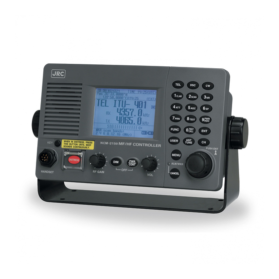
Page 46: Ncm-2150 Mf/Hf Controller
INSTALLATIONS 2.2.2 NCM-2150 MF/HF Controller 2.2.2.1 External dimensions and installation space 2-22... -
Page 47: Installation
INSTALLATIONS 2.2.2.2 Installation RS-485 signal line terminator settings The RS-485 lines are used for signals between the NTD-2150 MF/HF transceiver and the NCM-2150 MF/HF controller, so terminators must be placed on the first and last units. If there is only one MF/HF controller this setting is not necessary because the load is terminated (on) at the MF/HF controller at the factory. - Page 48 INSTALLATIONS Installation using the mounting bracket (MPBX44354) Refer to the following diagram to use the mounting bracket. Spacer Double-sided tape Spacer Knob bolt Knob bolt 2-24...
- Page 49 INSTALLATIONS Installation on the console (embedded) Installation hardware is not needed when embedding the controller in the console because the screws on the back of the MF/HF controller are used. Refer to the following diagram to cut holes in the console panel and install the MF/HF controller. 2-25...
- Page 50 INSTALLATIONS Installation using the flush mounting bracket (MPBC42957) Refer to the following diagram to use the flush mounting bracket. 2-26...
-
Page 51: Supplementary Materials
INSTALLATIONS 2.2.2.3 Supplementary materials CW keyer terminal When use a CW keyer, insert the key plug to the jack of the controller front panel (Φ3.5mm mini-plug). key jack for Φ3.5mm mini plug) Connecting an external speaker CAUTION Do not shorten the lines of the mini plug. Doing so may cause malfunction. Use the SP jack (Φ... - Page 52 INSTALLATIONS Information The red covered connector (Dsub-9 male) on the rear of the controller includes DC24V output pins. Do not remove the cover except to use an external modem and so on. If the cover is always removed and the power lines are shortened, it may cause a malfunction. 2-28...
-
Page 53: Handset
INSTALLATIONS 2.2.3 NQW-261 Handset 2.2.3.1 External dimensions Unit: Mass: Approx. 0.4 kg (handset only) Approx. 0.5 kg (including cradle) Color: Black 2-29... -
Page 54: Building The Connector For The Handset
INSTALLATIONS 2.2.3.2 Building the connector for the handset Step 1. Stripping Step 5. * Insert the lock nut (8) into the housing term inal. * The solder cable (6) is divided to contact positions in the housing * Insert the O-ring (7) onto the front end of the housing. Step 2. -
Page 55: Nqd-2250 Connection Box
INSTALLATIONS 2.2.4 NQD-2250 Connection Box 2.2.4.1 External dimensions Unit: Mass: Approx. 0.6 kg Color: Munsell N4 equivalent 2-31... -
Page 56: Installation
INSTALLATIONS 2.2.4.2 Installation Refer to the following diagram to install the connection box. 1. Remove the 4 screws (M4) holding the cover to the main unit and remove the Cover Main Screw 2. Fix the main unit to the wall with 4 screws (M4) and wire the terminal Screw Termina l block... -
Page 57: Connecting The Signal Lines
INSTALLATIONS 2.2.4.3 Connecting the signal lines Use the following method to connect the signal lines to terminals TB1 - 2, TB 11 - 12, and TB21 - 22 on the CQD-2250 connection board in the connection box. Note: Connections on the terminal board of the transceiver are the same. Slide a thin flathead screwdriver all the way into the ①... -
Page 58: Terminal Description
INSTALLATIONS 2.2.4.4 Terminal description TB1 - TB2 (CONTROLLER) Connection Name Description point Ground for shielded connections (Not used) DISP_LINE+ 600 Ω equalized, 0 dBm AF receiver signal DISP_LINE- DISP_KEY PTT/KEY line NCM-2150 SYS_RST System reset line MF/HF RS-485-A controller Interface for RS-485 communication (57.6 kbps) (No. -
Page 59: Nfc-2150 Antenna Tuner
INSTALLATIONS 2.2.5 NFC-2150 Antenna Tuner CAUTION Locate the antenna tuner, TX antenna and lead-in wire in locations as far as possible from people and surrounding structures to satisfy the following conditions. • Far at least 30cm beyond anyone’s reach. • Low vibration. -
Page 60: Antenna Tuner Installation
INSTALLATIONS 2.2.5.2 Antenna tuner installation Refer to the following diagrams for the antenna tuner installation. Furthermore for this installation, normally use the feeder kit (6ZPKD00073) and the installation materials (6ZPKD00074) mentioned on the next pages. To antenna Tension absorbing insulator Service mounting bracket Ship wall... - Page 61 INSTALLATIONS List Name DWG. NO Components list for attached parts Feeder Kit 6ZPKD00073 ITEM NAME OF OUTLINE TYPE Q’TY JRC CODE NO. PART (DIMENSION IN M/M) ( DESCRIPTION ) Insulator NG-159A MPNG00069 Shackle BP-O-58 MPXP0023W Thimble BRXP00845 Wire Clip PBC-3...
- Page 62 INSTALLATIONS List Name DWG. NO Components list for accessories Installation Materials 6ZPKD00074 ITEM NAME OF OUTLINE TYPE Q’TY JRC CODE NO. PART (DIMENSION IN M/M) ( DESCRIPTION ) Earth 6ZPKD00084 Terminal IRON COPPER Earth Bolt 6ZPKD00083 Earth Plate 6ZZKD01031 1200 COPPER 0.3t...
-
Page 63: Cable Processing
INSTALLATIONS 2.2.5.3 Cable processing Antenna tuner connections 100mm 70mm RF cable RFケーブル Control cable (7ZCJD0045) (7ZCJD0045) Fix the cable after ケーブル長を調整 adjusting the length. 後に固定する。 2-39... - Page 64 INSTALLATIONS RF relay cable connections Preparing tools: Cut the coating M-type coaxial connector Coaxial cable Soldering iron (60 - 80 W) ▸ Pb-free solder ▸ Knife (for coating/ insulation) ▸ ▸ Scissors (for the shield) Apply solder Tester ▸ Shield Cut the shielding and insulation First insert this part of...
-
Page 65: Wiring The Control Signal Lines
INSTALLATIONS 2.2.5.4 Wiring the control signal lines Antenna tuner terminal Use a flathead screwdriver to connect the signal lines as shown below. Loosen the screw with the screwdriver. ① ② Insert the control signal line. (Compatible wire sizes: 0.1 ~ 1.5 mm (AWG 30~14), stripped length: 6 mm) Tighten the screw with the screwdriver to fix the signal line. - Page 66 INSTALLATIONS Junction box terminal When using a junction box (NQD-2253) connect the signal lines as shown below. Antenna tuner Provided cable Corresponding cable:φ8.5 ~ φ10.5 Cable gland 15b NQD-2253 JUNCTION BOX Vinyl electrical wire 7 wires/0.45 mm or more Twist the shield and solder to vinyl wire. Cable gland 30a Corresponding cable:φ18.5 ~...
-
Page 67: Example Of Antenna Installation
INSTALLATIONS 2.2.5.5 Example of antenna installation Refer to the following diagrams for antenna installation for various types of antennas and ships. 2-43... - Page 68 INSTALLATIONS 2-44...
-
Page 69: Nqd-2253 Junction Box
INSTALLATIONS 2.2.6 NQD-2253 Junction Box 2.2.6.1 External dimensions Unit: Mass: Approx. 1.2 kg Note) For details of this junction box, refer to the above section. 2-45... -
Page 70: Nbd-2150 Ac/Dc Power Supply
INSTALLATIONS 2.2.7 NBD-2150 AC/DC Power Supply 2.2.7.1 External dimensions Unit: mm Weight: Approx. 9.8 kg CAUTION: The rack mount kit (7ZZJD0072) is needed for rack mounting. Additionally, when mounting it, always use the dedicated screws in the mount kit. 2-46... -
Page 71: Connecting The Signal Lines
INSTALLATIONS 2.2.7.2 Connecting the signal lines To wire the AC/DC power supply (NBD-2150), remove the top plate from the back of the main unit and connect the wires to the terminal board as shown below. When wiring is finished, secure the wires in bundles with a cable clamp. -
Page 72: Battery Charger
INSTALLATIONS 2.2.8 NBB-724 Battery Charger 2.2.8.1 External dimensions and installation space To use the bottom bracket to install the charger, install it as shown below using the bottom bracket provided. Bottom bracket (provided) Unit: Mass: Approx. 12.0 kg Note: The rack mount kit (7ZZJD0073) is needed for rack mounting. 2-48... -
Page 73: Connecting The Signal Lines
INSTALLATIONS 2.2.8.2 Connecting the signal lines Use the specialized cables as shown below to connect the charger (NBB-724). BATT BATT OUT AC IN Battery NBD-2150 AC110V/ DC24V DC24V IN AC220V 200Ah 2-49... -
Page 74: Setting The Ac Input Voltage (110 Vac/220 Vac)
INSTALLATIONS 2.2.8.3 Setting the AC input voltage (110 VAC/220 VAC) Open the cover on the back panel indicated by the arrow in the drawing and use the short plug to switch the AC input voltage according to the setup manual provided. The factory setting is 220 VAC. Termin al block After setting the AC input voltage, remove the appropriate label for the input voltage from the voltage switching tag ((1) on the following page) and stick it in the box on the voltage label ((2) on the following... - Page 75 INSTALLATIONS (2) Voltage display label ② 電圧表示ラベル (1) Voltage switching tab ① 電圧切替タグ Cut out 2-51...
-
Page 76: Setting The Battery Charging Voltage
INSTALLATIONS 2.2.8.4 Setting the battery charging voltage The charger (NBB-724) is set at the factory for lead acid batteries. To use other types of batteries, set it as shown below. Reference: Battery types and charging voltages Type Model number Floating charge voltage Equalizing charge voltage Lead SS-200... - Page 77 INSTALLATIONS ④ After setting the floating charge voltage, move switch SW2 up to light the EQUAL lamp shown below, to turn on equalizing charge mode. Caution: Equalizing charge mode can be turned on by using the CHARGE switch on the panel, but if the charge voltage goes below 3A it automatically returns to float charge.
-
Page 78: Details On Switches And Controls In The Blank Panel
INSTALLATIONS 2.2.8.6 Details on switches and controls in the blank panel Functions and explanations of switches and controls in the blank panel are shown below. Factory Functions Setting Status after configuration default Equalizing charge timer Normal setting (timeout 10 h) (for factory testing) Down Test setting... - Page 79 INSTALLATIONS Functions Factory setting Floating charge voltage adjustment control 26.2 V Equalizing charge voltage adjustment control 29.4 V Charging voltage adjustment control when BATT LOW TEMP detected 27.5 V Charging voltage adjustment control when BATT HI TEMP detected 25.3 V Floating charge voltage adjustment control Used when adjusting the floating charge voltage.
-
Page 80: Accessory Terminals
INSTALLATIONS 2.2.8.7 Accessory terminals Functions and explanations of the accessory terminal located on the back panel are shown below. Name Description BATT VOLT (+) BATT OUT voltage monitor output (max. 1.0 A) BATT VOLT (-) BATT CURR (+) Outputs voltage proportional to the charge and discharge voltage as an analog value BATT CURR (-) DC OPE... - Page 81 INSTALLATIONS Low voltage detection function When a drop in battery voltage (21.5 V or less) is detected, the BATT LOW VOLT LED lights and a buzzer sounds. Does not operate for momentary voltage fluctuations from sudden currents when starting the device due to 0.1 to 0.5 second hysteresis. * Auto recovery when the battery voltage goes above 23.5 V.
-
Page 82: Printer
INSTALLATIONS 2.2.9 NKG-91 Printer 2.2.9.1 External dimensions and installation when attached to a wall External dimensions (using MPBP31446) Installation hole Wiring hole (back) Wiring hole (side) Unit: Mass: Approx. 1.5 kg Color: Munsell N4 2-58... - Page 83 INSTALLATIONS Installation Use the MPBP31446 and refer to the diagram below to install it. M4 screw 2-59...
-
Page 84: External Dimensions And Installation For A Flush Mount
INSTALLATIONS 2.2.9.2 External dimensions and installation for a flush mount External dimensions Unit: Mass: Approx. 0.8 kg Color: Munsell N4 2-60... - Page 85 INSTALLATIONS Installation Refer to the diagram below during installation. Installation hole (Unit: mm) Installation side cut dimensions 2-61...
-
Page 86: Connecting The Signal Lines
INSTALLATIONS 2.2.9.3 Connecting the signal lines • Back of NKG-91 main unit Connector terminal wiring example for power source Signal name Direction Functions DC + DC + Input power source DC - DC - Input power source Serial connector Ground -... -
Page 87: Printer (Desktop Type)
INSTALLATIONS 2.2.10 NKG-414 Printer (desktop type) 2.2.10.1 External dimensions and installation space Velcro (Provided) Unit: Mass: Approx. 0.6 kg Color: Ivory 2-63... -
Page 88: Connecting The Signal Lines
INSTALLATIONS 2.2.10.2 Connecting the signal lines • Back of DPU-414 Printer power cable Printer cable DC 6.5 V, 2 A Printer cable: 7ZCJD0254A (1.5 m) Printer power cable: 7ZCJD0257C (1.5 m) • Back of MF/HF controller (NCM-2150) Serial connector cover Printer power cover Remove the serial connector cover and the cover over the printer power source. -
Page 89: Printer (Centronics Compliant/Desktop Type)
INSTALLATIONS 2.2.11 NKG-800 Printer (Centronics compliant/desktop type) 2.2.11.1 External dimensions and installation space Over 以上 Over 以上 Unit: Mass: Approx. 3.7 kg Note: When installing the NKG-800 printer, fix it with the Velcro attached to the bottom. 2-65... -
Page 90: Connecting Power Supply And The Signal Lines
INSTALLATIONS 2.2.11.2 Connecting power supply and the signal lines • Back of MF/HF controller (NCM-2150) When connecting the NKG-800 printer, set the printer power of the controller to DC24V as follows. ① Remove the back cover (shaded area in diagram) and use the AF CONT UNIT (CMV-3775) jumper pin (TB1) to set the terminator to 2-3 side (DISP_PWR) -
Page 91: Setting The Dip Switches
INSTALLATIONS 2.2.11.3 Setting the DIP switch When connecting the printer (NKG-800) to the JSS-2150, set the DIP switches as follows. Open the printer cover, remove the ink ribbon cartridge, and use your hand to move the print ① head to the far right. - Page 92 INSTALLATIONS 2-68...
-
Page 93: Appendix
APPENDIX 3. APPENDIX 3.1 Block diagram 3.1.1 NTD-2150 MF/HF TRANSCEIVER... -
Page 94: Cah-2415 Pa Unit
APPENDIX 3.1.2 CAH-2415 PA UNIT NAND... -
Page 95: Cmn-2250 Trx Unit
APPENDIX 3.1.3 CMN-2250 TRX UNIT LINE EXT MODEM KEY MODEM SEL TUNE KEY PA RDY PLL RST TX RDY TRX MAIN SCAN STOP IN SCAN STOP DISP KEY OUT DDS RST BK OUT F DAC RST BK ERR ERR485 D3R3V DUP BK OUT DUP BK DUP BK IN... -
Page 96: Cmj-2250 Wkr Modem Unit
APPENDIX 3.1.4 CMJ-2250 WKR MODEM UNIT... -
Page 97: Ncm-2150 Mf/Hf Controller
APPENDIX 3.1.5 NCM-2150 MF/HF CONTROLLER... -
Page 98: Nfc-2150 Antenna Tuner (Cfg-2150 Matching Unit)
APPENDIX 3.1.6 NFC-2150 ANTENNA TUNER ( CFG-2150 MATCHING UNIT... - Page 99 APPENDIX...
- Page 100 APPENDIX...
- Page 101 APPENDIX...
- Page 102 APPENDIX 3-10...
- Page 103 APPENDIX 3-11...
- Page 104 APPENDIX 3-12...
- Page 105 APPENDIX 3-13...
- Page 106 APPENDIX 3-14...
- Page 107 APPENDIX 3-15...
- Page 108 APPENDIX 3-16...
- Page 109 APPENDIX 3-17...
- Page 110 APPENDIX 3-18...
- Page 111 APPENDIX 3-19...
- Page 112 APPENDIX 3-20...
- Page 113 APPENDIX 3-21...
- Page 114 APPENDIX 3-22...
Need help?
Do you have a question about the JSS-2150 and is the answer not in the manual?
Questions and answers