Table of Contents
Advertisement
Quick Links
Installation and Servicing
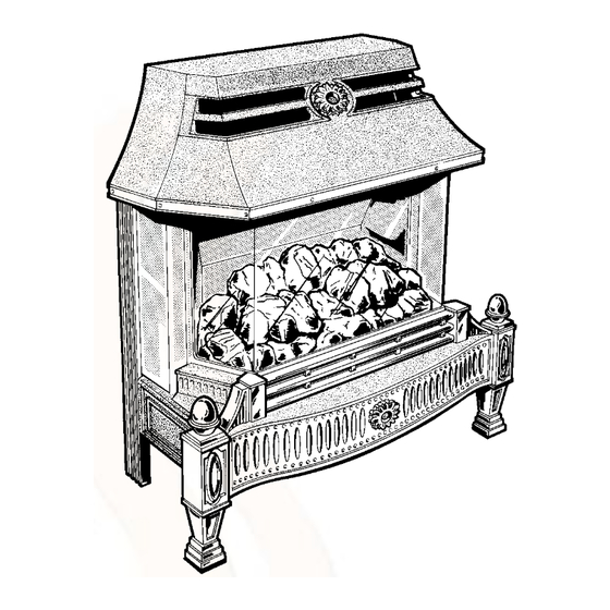
BBU Fire Front
F o r u s e w i t h
5 6 / 3 e , 5 6 / 3 p p , 4 5 / 2 a n d 5 6 / 2
s p e c i a l l y d e s i g n e d
B a c k B o i l e r U n i t s o n l y
G.C. No. 37 047 08
This is a Cat I
Reference in these instructions to British Standards and Statutory
Regulations/Requirements apply only to the United Kingdom.
For Ireland the rules in force must be used.
The instructions consist of three parts, User, Installation and Servicing Instructions, which includes the Guarantee Registration
Card. The instructions are an integral part of the appliance and must, to comply with the current issue of the Gas Safety
(Installation and Use) Regulations, be handed to the user on completion of the installation.
Thank you for installing a new Glow-worm appliance in your home.
Glow-worm appliances' are manufactured to the very highest standard so we are pleased
to offer our customers' a Comprehensive First Year Guarantee.
In the centre pages are to be found your Guarantee Registration Card, which we recommend you complete and
If this card is missing you can obtain a copy or record your registration by telephoning the Heatcall Customer
Our Guarantee gives you peace of mind plus valuable protection against breakdown by covering the cost of:
All replacement parts
All labour charges
All call-out charges
One Contact Local Service
Supplied By www.heating spares.co Tel. 0161 620 6677
Instructions for Use
To b e l e f t w i t h t h e u s e r
BS 6332
BS 5258
Appliance
2H
Guarantee Registration
return as soon as possible.
Service number 01773 828100.
REGISTER YOUR GLOW-WORM APPLIANCE
FOR 1ST YEAR GUARANTEE PROTECTION
CALL 0181 380 2555
Customer Services:
Tel: (01773) 828100
Fax: (01773) 828070
Hepworth Heating Ltd.,
Nottingham Road, Belper, Derbyshire. DE56 1JT
General/Sales enquiries:
Tel: (01773) 824141 Fax: (01773) 820569
221793A. 06. 00
Advertisement
Table of Contents

Related Manuals for Glow-worm Black Ash 3


Summary of Contents for Glow-worm Black Ash 3
- Page 1 Guarantee Registration Thank you for installing a new Glow-worm appliance in your home. Glow-worm appliances' are manufactured to the very highest standard so we are pleased to offer our customers' a Comprehensive First Year Guarantee. In the centre pages are to be found your Guarantee Registration Card, which we recommend you complete and return as soon as possible.
-
Page 2: Table Of Contents
Important Information CE Mark The CE mark on this appliance shows compliance with: 1. Directive 90/396/EEC on the approximation of the laws of the Member States relating to appliances burning gaseous fuels. 2. Directive 73/23/EEC on the harmonization of the Laws of the Member States relating to electrical equipment designed for use within certain voltage limits. - Page 3 This appliance is for use only on G20 gas. fitted and when redecorating. The Glow-worm Black Ash 3 BBU gas fire front is to be used The glass panel on this fire front conforms to the requirements with specially designed Glow-worm 56/3e, 56/3pp, 45/2, 56/2, of the current issue of BS1945 and satisfies the Heating 45, 56, 45R or 56R Back Boiler Units only.
- Page 4 Instructions for Use Maintenance To ensure the continued efficient and safe operation of the appliance it is recommended that it is checked and serviced at regular intervals. The frequency of servicing will depend upon the particular installation and usage, but in general once a year should be enough.
- Page 5 Instructions for Use Adjust the control thermostat knob “A” to the required setting Lighting the Boiler (BBU 56/3e ONLY) between "MIN" and “MAX”. This appliance is fitted with a flue blockage safety device which “MAX” is approximately 82°C. will shut down the appliance in the event of abnormal flue conditions.
- Page 6 Instructions for Use NOTE. If the burner does go out, wait three minutes before Lighting the Boiler (BBU 56/3pp ONLY) relighting. For any other reason, wait two minutes before This appliance is fitted with a flue blockage safety device which relighting the burner.
- Page 7 Instructions for Use If the pilot burner fails to stay alight turn gas control knob “A” Lighting the Boiler (45/2 and 56/2 ONLY) “Off”, that is, fully clockwise. Wait three minutes. Repeat the This appliance is fitted with a flue blockage safety device which lighting operation, only now keep the control knob “A”...
- Page 8 15 seconds then release. Check that the pilot is still As this fire front may be fitted to a Glow-worm 45, 56, 45R alight, look through window “F”. or 56R back boiler unit WITHOUT a flue blockage safety If the pilot burner fails to stay alight turn gas control knob “A”...
- Page 9 Instructions for Use Lighting the Fire Front CAUTION. If the glass panel or internal fire parts are damaged do not light or use the fire front before replacement parts are fitted. The fire front is fitted with a flue blockage safety device which will shut it down if there is a problem with the chimney.
- Page 10 Instructions for Use the use of a normal domestic vacuum cleaner, which may blow Glass Panel and Internal Fire Front Parts dust back into the air. Remove the canopy as diagram 8. Take care as it is made of CAUTION. If replacing use only the fuel effect pieces approved cast iron.
- Page 11 Instructions for Use FUEL Left Right FUEL EFFECT PIECE POSITION 3 EFFECT Side Side BASE (see note) RETAINING BRACKETS FUEL EFFECT LOCATION BASE LUG 3 NOTE: SUPPORT ANGLE FOR Fuel Effect Base NOTE: FUEL EFFECT PIECE MUST FUEL EFFECT PIECES seats behind SIT ON SUPPORT ANGLE 1, 2 AND 3...
- Page 12 Replacement Parts If replacement parts are required apply to your local supplier. Please quote the name of the fire front, “Black Ash 3 BBU”, to be found on the control knob bezel. The back boiler serial number can be found on the base after removal of the plinth.
- Page 13 An additional cause could be that the filter, in the gas tap has become The Glow-worm Black Ash 3 BBU gas fire front is to be used with blocked. Any problems found must be put right by a competent specially designed Glow-worm 56/3e, 56/3pp, 45/2, 56/2, 45, person, before the fire front is used again.
- Page 14 1 General 1.3 Data Gas connection - from the service cock Total weight - 49kg Bray 18/180 Injector - upper - Bray 18/320 - lower - Burner pressure setting - cold - 13.0mbar 5.2in wg 13.2 mbar 5.3in wg - hot - 6.7kW - 22,750Btu/h Heat input - gross...
-
Page 15: Types Of Flue Installation
2 Types of Flue and Installation Note. Refer to Section 2 in the Back Boiler Installation book before starting. 2.1 With Hearth A fireproof hearth under the fire front must have the minimum dimensions as shown in diagram 2.1. 2.2 With Surround See diagram 2.2. -
Page 16: Fire Front Preperation
3 Fire Front Preperation FIRE BODY PACK FIRE BODY ASSEMBLY FLUE SPIGOT FUEL EFFECT COMBUSTION CHAMBER BOTTOM PLATE WALL SEALING PLATE CASING PACK CANOPY R.H. SIDE L.H. SIDE PANEL PANEL FRONT CASTING R.H. SIDE CASTING L.H. SIDE CASTING R.H. LEG PLINTH LOOSE ITEMS... - Page 17 3 Fire Front Preperation SCREW FRONT LEG M5x30 LEVELLING SCREW SCREW SIDE CASTINGS M5x14 REAR FIXING SCREW UPPER WALL M5x40 MOUNTING ANCHOR UPPER WALL MOUNTING SCREW FRONT LEG M4x8 FIXING SCREW WALL SEALING No. 10 x 1 PLATE FIXING WALL WALL SEALING PLUG PLATE FIXING...
- Page 18 3 Fire Front Preperation 3.1 Unpacking FLUE SPIGOT ASSEMBLY The fire front is delivered in two packs, one contains the body assembly. The other contains the fire front castings, and loose items pack. Refer to diagrams 3.1 and 3.2. to identify the parts. To unpack carton 1, lift out the top fitting containing the fire spigot and combustion chamber bottom plate, lift out the cardboard front fitting, the supply tube pack and the two boxes...
- Page 19 3 Fire Front Preparation 3.4 Gas Supply to Fire Front (Fitting to 56/3e and 56/3pp Back Boiler Units ONLY) GAS SERVICE COCK Check that gas service cock on the boiler is in the Off position, see diagram 3.4. The inlet supply tube is packed with the fire front and will require cutting to fit the gas service cock on the back boiler unit.
-
Page 20: Installation
4 Installation 4.1 Positioning the Fire Front (Fitting to 56/3e MARK and 56/3pp Back Boiler Units ONLY) FRONT Place the wall sealing plate onto the back boiler air duct, mark FIXING the fixing holes, remove the plate and drill the holes to suit the HOLES plugs and screws provided, in the supply tube pack, leave sufficient screw proud to accept the wall sealing plate keyholes,... - Page 21 4 Installation 4.3 Gas Connection (Fitting to 56/3e and 4.4 Back Boiler Sensing Tubes (Fitting to 45/2 56/3pp Back Boiler Units ONLY) and 56/2 Back Boiler Units ONLY) Place the tubing nut and olive, from the loose items pack, onto Note: The gas supply tube, see diagram 4.9, is supplied with the the prepared end of the gas supply tube, see diagram 4.9.
- Page 22 4 Installation 4.5 Positioning the Fire Front (Fitting to 45/2 4.7 Gas Connection (Fitting to 45/2 and 56/2 and 56/2 Back Boiler Units ONLY) Back Boiler Units ONLY) Place the fire front onto the back boiler air duct, check that the Place the tubing nut and olive, from the loose items pack, onto fire front flue spigot is central in the flue collector assembly, push the prepared end of the gas supply tube, see diagram 4.9.
- Page 23 4 Installation LOCK NUT (A) UNION NUT (B) JOINT (C) GAS SUPPLY PIPE GAS SERVICE COCK TUBING OLIVE Diagram 4.9 UPPER UPPER SIDE SIDE FIBRE RETAINING RETAINING FIBRE WASHER SCREW SCREW WASHER R.H. SIDE LOCATING PIN PANEL AND HOLE GAS CONTROL KNOB R.H.
-
Page 24: Lighting, Testing And Fitting Internal Parts
5 Lighting, Testing and Fitting Internal Parts 5.1 Lighting and Testing Make sure that the electrical supply to the back boiler is isolated. This fire front is fitted with a flue blockage safety device which will shut down the fire if there is an unacceptable spillage of products at the draught diverter. - Page 25 5 Lighting, Testing and Fitting Internal Parts 5.5 Test for Clearance of Products 5.2 Internal Parts - Fitting Notes Caution. If any of the internal fire front parts are damaged DO NOT light or further test the fire front until replacement parts are WARNING.
- Page 26 5 Lighting, Testing and Fitting Internal Parts LOCATION SLOT FOOT LOCATION PIN VIEWED FROM REAR LEVELLING SECURING SCREW SCREW (2) Diagram 5.4 SIDE CASTING FRONT CASTING Diagram 5.6 SECURING SCREW (3) M5 x 14mm Diagram 5.5 221793A Supplied By www.heating spares.co Tel. 0161 620 6677...
- Page 27 5 Lighting, Testing and Fitting Internal Parts DRAUGHT DRAUGHT DIVERTER DIVERTER L.H. SIDE L.H. SIDE PANEL PANEL SMOKE SMOKE MATCH MATCH EMPLUME EMPLUME TUBE TUBE TORCH TORCH SMOKE MATCH SMOKE MATCH AND EMPLUME AND EMPLUME TUBE TUBE (45/2 and 56/2 ONLY) Diagram 5.7 (56/3e and 56/3pp ONLY) Diagram 5.9...
-
Page 28: Instructions For Use
6 Instructions for Use Hand these instructions the user and instruct in the safe and Advise the user of the precautions necessary to prevent damage economical use of the fire front and back boiler. to the system, boiler and the building, in the event of the heating system being out of use during frost or freezing conditions. - Page 29 7 Servicing and Replacement of Parts 7.3 Burner and Injectors Remove the front casting, see diagram 5.6. Remove the lower front baffle, see diagram 7.1. Remove the burner baffle, see diagram 7.1. Remove the RH. leg, see diagram 5.4. Remove the side castings, see diagram 5.5. Remove the RH.
- Page 30 7 Servicing and Replacement of Parts L.H. BURNER R.H. BURNER SECURING SCREW SECURING SCREW TUBE BURNER UNION UNION CONNECTION CONNECTION FLUE BLOCKAGE UNION SAFETY DEVICE CONNECTION NOTE: Chamfered edge to be on Diagram 7.3 this side. MOUNTING BRACKET BURNER PULL FORWARDS SECURING SCREW (2) Diagram 7.4...
- Page 31 7 Servicing and Replacement of Parts ELECTRODE GAS TAP MOUNTING BRACKET SECURING SCREW EARTH SPARK GAP POST + 1.0 - 0.5 MICRO SWITCH ELECTRICAL CONNECTIONS EARTH INSULATION ELECTRODE POST MICRO SWITCH NUT (2) TOP VIEW GAS TAP MOUNTING ELECTRODE BRACKET INSULATION SECURING SCREW (2)
- Page 32 7 Servicing and Replacement of Parts GAS TAP SECURING SCREWS THERMOCOUPLE Diagram 7.9 Diagram 7.10 GAS TAP BODY GAS TAP BRACKET AND PLUG NITING PLATE ASSEMBLY 'O' RING FILTER WASHER SPRING FILTER GAS TAP BODY CROSS SECTIONAL VIEW SECURING SCREW Diagram 7.11 221793A Supplied By www.heating spares.co Tel.
-
Page 33: Fault Finding
8 Fault Finding 8.4 Flue blockage safety device 8.1 Fire Front Ignition If the device operates it indicates there could be a problem with Remove decorative castings, glass panel and fuel bed, refer to the chimney or, the pilot filter in the gas tap is blocked. First appropriate parts of Section 7. - Page 34 8 Fault Finding START HERE FIRE WILL NOT LIGHT Check that gas is available Does the pilot light using a match ? Turn off appliance tap, turn on appliance tap. Change pilot filter Does the fire light ? Ensure gap is within specified Check that gas is available at burner, using a tolerance, refer to SERVICING.
- Page 35 8 Fault Finding Disconnect appliance thermocouple from the gas tap. Check that all connections are clean and in good condition. Fit test meter interrupter into the magnet unit. Fit appliance thermocouple into the test meter interrupter. Hold down control tap in ignition position. Ignite burner, allowing thermocouple to attain operating temperature.
-
Page 36: Replacement Parts
Unless stated otherwise reassembly of all parts is in the reverse order to removal. When replacement of parts are required please apply to your local supplier. Please quote the name of the fire front, “Black Ash 3 BBU”. The GC number can be found on the chassis, visible when front casting is removed.
Need help?
Do you have a question about the Black Ash 3 and is the answer not in the manual?
Questions and answers