Table of Contents
Advertisement
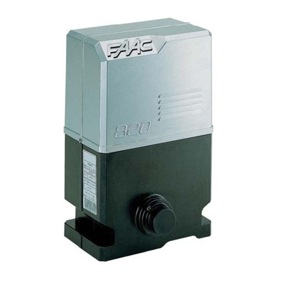
The 820/860 Slide Gate
Operator: Installation Manual
Important Safety Information........................................................................2
Technical Data ..............................................................................................4
Unpacking the Operator ................................................................................5
The 820/860 Slide Gate Operator..................................................................6
General Characteristics .............................................................................6
Operating Logic ........................................................................................7
Manual Release Mechanism..................................................................7
E1 (Semi-Automatic 1) Mode ...............................................................8
E2 (Semi-Automatic 2) Mode ...............................................................8
A1 (Automatic 1) Mode ........................................................................8
A2 (Automatic 2) Mode ........................................................................9
S1 (Security) Mode ...............................................................................9
S2 (Security Plus) Mode .......................................................................9
B Mode..................................................................................................9
C Mode..................................................................................................9
Installation Instructions ...............................................................................11
Set the Forms for the Conduit and Concrete ..........................................11
Ground Mounting................................................................................11
Cantilevered Mounting........................................................................11
Mount the Operator on the Foundation Plate .........................................11
Chain Operator ....................................................................................11
Rack and Pinion Operator ...................................................................12
Connect the Electrical Power .................................................................14
Set the DIP Switches ...............................................................................15
Operating Logic...................................................................................16
Pause Time ..........................................................................................16
Warning Light Operation ....................................................................17
Gate Orientation ..................................................................................17
Set the Limit Switches.............................................................................17
Define the Midpoint ............................................................................18
Set the Opened Limit...........................................................................19
Set the Closed Limit ............................................................................19
Relocating the Midpoint......................................................................19
Install Other Accessories.........................................................................20
Remove the Bleed Screw ........................................................................21
Adjust the Clutch of the Operator ...........................................................22
Maintenance ................................................................................................23
Troubleshooting ..........................................................................................24
Exploded View, 820/860 Mechanical Parts ................................................25
Exploded View, 820/860 Electronic Parts ..................................................26
FAAC International, Inc.
303 Lexington Avenue
Cheyenne, WY 82007
www.faacusa.com
Contents
Advertisement
Table of Contents

Related Manuals for FAAC 820


Summary of Contents for FAAC 820
-
Page 1: Table Of Contents
Install Other Accessories.................20 Remove the Bleed Screw ................21 Adjust the Clutch of the Operator ............22 Maintenance ....................23 Troubleshooting ..................24 Exploded View, 820/860 Mechanical Parts ..........25 Exploded View, 820/860 Electronic Parts ..........26 FAAC International, Inc. 303 Lexington Avenue Cheyenne, WY 82007... -
Page 2: Important Safety Information
Important Safety Information Both the installer and the owner and/or operator of your gate and its operator are well-designed, installed this system need to read and understand this correctly, and used safely. installation manual and the safety instructions Gate Design supplied with other components of the gate system. - Page 3 8. To guarantee the efficiency of this equipment, the to your supply voltage. Refer to the label on your manufacturer recommends that qualified personnel operator system. periodically check and maintain the equipment. U.L. Class and FAAC Operator Duty Cycle Typical Use Model Class I: Residential Vehicular Gate Operator Limited duty •...
-
Page 4: Technical Data
Operator weight, lb (kg) 31 (14) 34 (15) Oil type FAAC XD 220 or Shell/Tellus #15 Oil quantity, qt (l) 1 (0.9) Motor run time may vary if gate and operator are not installed properly. Measured at 220 volts and at 72 deg F (22 deg C). Increased or decreased voltage affects pulling forces respectively. -
Page 5: Unpacking The Operator
Unpacking the Operator When you receive your 820 or 860 Operator (see Figure 1), complete the following steps. Operator carton 1 Operator included with customer-ordered chain drive or rack and pinion drive Inspect the shipping box for physical damage such as leaking oil or a torn carton. -
Page 6: The 820/860 Slide Gate Operator
General Characteristics requiring extra strength are made of steel or cast iron. The 820 and 860 Slide Gate Operators are compact The motor for the 820 or 860 Operator serves as a gate operators with GentleSlide Motion Management for lock. For further reliability, the motor's armature shaft is high-traffic applications. -
Page 7: Operating Logic
Safety features on the 820 or 860 Operator include an adjustable, oil-immersed clutch that is designed to help provide anti-crush protection for both pedestrians and property, as well as for the gate system itself. -
Page 8: E1 (Semi-Automatic 1) Mode
The E1 (semi-automatic 1) mode of operation for the The E2 (semi-automatic 2) mode of operation is like E1 820/860 Operator is designed for users who want to except in the way the gate leaf responds while closing signal the gate to either open or close. Sending one with reversing devices installed. -
Page 9: A2 (Automatic 2) Mode
During the pause phase of S2 logic, a triggered Installing reversing devices has the following effects reversing device interrupts the pause count but does not on the logic of A1 mode: During the opening phase, reset the pause count. The gate continues its pause a triggered reversing device is ignored;... - Page 10 E1 Logic: How the gate leaf behaves S1 Logic: How the gate leaf behaves Leaf Signal Leaf Signal status Stop Reversing status Stop Reversing Open or A/C Open or A/C Closed Opens no effect no effect Closed Opens, pauses, no effect no effect and closes Open...
-
Page 11: Installation Instructions
For a cantilevered gate installation in which you supply 820/860 Operator. your own mounting plate and pedestal, keep the Before you install the 820 or 860 Operator, you must following in mind: insure that the gate leaf falls within the limitations outlined in the section "Technical Data."... -
Page 12: Rack And Pinion Operator
Leveling bolt or 18 in. (45.7 cm) minimum Foundation plate leg extends into the concrete 3 5/8 in. (9.2 cm) Figure 4. The concrete footing and 820/860 Operator in relation to the gate leaf: (a) top view and (b) side view... - Page 13 (a) Welding a rack spacer to the gate leaf through the foundation plate Bend the legs down so they are vertical. Bend the feet on the legs to a horizontal orientation. Figure 5. Preparing the optional FAAC foundation plate Outside U bolt (2 required)
-
Page 14: Connect The Electrical Power
3. 3-button switch 4. Warning lamp 4. Warning lamp 5. Switch 5. Switch 6. Main power circuit breaker 6. Main power circuit breaker 7. Junction box 7. Junction box Figure 10. Typical gate system layout for an 820 or 860 Operator... -
Page 15: Set The Dip Switches
820 or 860 Operator; the figure also • The operating logic of the operator lists the required wire gauges between gate • The pause time of the gate leaf between components. Figure 11 shows the wiring necessary opening and closing between the operator and the main power source. -
Page 16: Operating Logic
Decoder connector (OPEN) Open LED Low-voltage terminal Block (A/C) Partial open/close LED ADL connector (STOP) Stop LED FAAC lamp output terminal block (FTSW) Safety LED Capacitor connector (ADL) Limit switch alarm LED Electric motor connector (FCA) Opening limit switch LED... -
Page 17: Warning Light Operation
Switch S8 is used to set the gate's orientation. You must Warning Light Operation set switch S8 before you set the limit switches for fully The function of a warning light depends on how you opened and fully closed positions of the gate leaf. connect the light to the 826 MPS terminal strip and how you set DIP switches S6 and S7. -
Page 18: Define The Midpoint
You have to define the gate leaf's midpoint, its fully Define the Midpoint opened position, and its fully closed position for the Move the gate leaf by hand to exactly the half-opened internal limit switches. position. The longer your gate leaf, the more important it is that you be precise in positioning the gate leaf To set the limit switch module, be sure the gate is in exactly at the half-opened position. -
Page 19: Set The Opened Limit
Next, you can set the fully opened and fully closed You should then hear one click from the panel and see positions for the gate leaf. You may set the limit the ADL status indicator LED blink once. Also, the switches in either order, but be sure to set both limit FCC LED should go out to further confirm that the switches. -
Page 20: Install Other Accessories
Terminals 11 and 12 supply high-voltage power when the motor is running. You connect your main power You install other accessories to the 820 or 860 Operator source to terminals 13 and 14. according to the terminal wiring diagram shown in Figure 15. -
Page 21: Remove The Bleed Screw
"breathe." adjustment screw on the 820 or 860 Slide Gate Operator for two reasons (see Figure 17): You should save the plastic cap in case you ever transport the operator. -
Page 22: Adjust The Clutch Of The Operator
Adjust the Clutch of the Faac International, Inc., recommends that the gate should stop all movement if it enounters a force aof Operator about 33 lb. (15 kg). Once you have adjusted the clutch, do not replace the WARNING! Turn the main power off before cap over the drive shaft. -
Page 23: Maintenance
Fill the inside the 820 or 860 operator. A dip stick is attached to operator with oil (about 1 qt [0.9 liter]) and reassemble the bottom of the oil cap for checking the oil. -
Page 24: Troubleshooting
Troubleshooting WARNING! Turn the main power off before you make any electrical connections or set any switches inside the operator. Status indicator LEDs under normal conditions LEDs Normal conditions: OPEN STOP FTSW (LD5) (LD6) (LD7) (LD8) (LD1) (LD2) (LD3) (LD4) Gate is closed Gate is fully opened Gate is half opened... - Page 27 Neither FAAC S.p.A. or FAAC International, Inc., assumes nor authorizes any person to assume for them any other liability in connection with the sale or use of the products of FAAC S.p.A. or FAAC International, Inc. The warranty hereinabove set forth shall not be deemed to cover maintenance parts, including, but not limited to, hydraulic oil, filters, or the like.
Need help?
Do you have a question about the 820 and is the answer not in the manual?
Questions and answers