Table of Contents
Advertisement
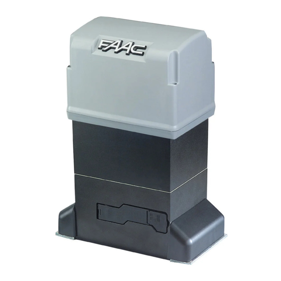
844 Compact Slide
Gate Operator:
Installation Manual
Important Safety Information........................................................................2
844 Technical Data .......................................................................................4
Unpacking the Operator ................................................................................5
The 844 Compact Slide Gate Operator .........................................................6
General Characteristics .............................................................................6
Operating Logic ........................................................................................6
B Mode..................................................................................................6
C Mode..................................................................................................6
BC Mode ...............................................................................................6
CB Mode ...............................................................................................6
E1 (Semi-Automatic) Mode ..................................................................6
A1 (Automatic) Mode ...........................................................................7
S1 (Security) Mode ...............................................................................7
S2 (Security Plus) Mode .......................................................................7
Manual Release Mechanism..................................................................7
Installation Instructions.................................................................................9
Setting the Concrete Forms.......................................................................9
Mounting the Operator............................................................................10
Chain Operator....................................................................................10
Rack and Pinion Operator ...................................................................10
Setting Up the Limit Switches ...............................................................13
Checking the Motor's Direction of Rotation...........................................17
Adjusting the Braking .............................................................................17
Connecting Other Accessories ................................................................17
Adjusting the Clutch Torque..................................................................17
Setting the DIP Switches.........................................................................18
The 844 B/C Control Panel .................................................................18
The 844 MPS Control Panel ...............................................................18
Finishing the Installation.........................................................................18
Maintenance ................................................................................................19
Troubleshooting ..........................................................................................20
Exploded View, 844....................................................................................23
www.faacusa.com
Contents
Advertisement
Table of Contents

Related Manuals for FAAC 844


Summary of Contents for FAAC 844
-
Page 1: Table Of Contents
844 Compact Slide Gate Operator: Installation Manual Contents Important Safety Information................2 844 Technical Data ..................4 Unpacking the Operator ................5 The 844 Compact Slide Gate Operator ............6 General Characteristics ................6 Operating Logic ..................6 B Mode....................6 C Mode....................6 BC Mode ....................6 CB Mode ....................6 E1 (Semi-Automatic) Mode ..............6... -
Page 2: Important Safety Information
Important Safety Information Both the installer and the owner and/or operator of correctly, and used safely. this system need to read and understand this Gate Design installation manual and the safety instructions 1. A gate is a potential traffic hazard, so it is im- supplied with other components of the gate system. - Page 3 Refer to the label on your 8. To guarantee the efficiency of this equipment, the operator system. manufacturer recommends that qualified personnel periodically check and maintain the equipment. U.L. Class and FAAC Operator Duty Cycle Typical Use Model Class I: Residential Vehicular Gate Operator Limited duty •...
-
Page 4: 844 Technical Data
Logics available: B, C, B/C, and C/B (see page 6) You may install either of the following control panels Maximum motor run time: 240 sec with the 844 Operator. Both the control panel and the operator require the same power supply voltage, 220 844 MPS VAC. -
Page 5: Unpacking The Operator
Covers for wiring access holes inside the damage before you can file a claim. operator If you have ordered a chain version of the 844 2. As you unpack the operator, insure that all parts Operator, you also have 1 chain kit with the following are included. -
Page 6: The 844 Compact Slide Gate Operator
The 844 Operator functions with either the 844 B/C available in a rack and pinion or a chain model. The control panel or the 844 MPS control panel. The two operator comes as a package containing the drive unit panels provide two different sets of operating logics: •... -
Page 7: A1 (Automatic) Mode
S2 (Security Plus) Mode to close. For example, one input signal makes the gate Available only on the 844 MPS control panel, the S2 open, and it remains open until another input signal is mode of operation is similar to the S1 mode with received, when the gate closes. - Page 8 E1 mode: How the gate leaf behaves for a given S1 mode: How the gate leaf behaves for a given signal signal Leaf Activating Stop Signal Reversing Leaf Activating Stop Signal Reversing Status Signal Device Status Signal Device closed opens no effect no effect closed...
-
Page 9: Installation Instructions
Also, the foundation plate will be centered size of the concrete footing. on all sides of the top of the concrete footing, and the 844 Operator will be centered on all sides of the Within the concrete forms, you need to locate the foundation plate. -
Page 10: Mounting The Operator
Set the height of the gate chain brackets so that the Now you are ready to mount the 844 Operator on its center of the idler sprockets (located on either side of foundation plate. Follow the instructions below that the drive sprocket) is even with the center line of the apply to the version of the operator you are installing. - Page 11 3/16 in. (0.5 cm) maximum 4 3/4 in. (12.1 cm) between the top of the rack and the bottom of the 844 Operator 2 3/8 in. (6 cm) between the bottom of the operator and ground level 2 3/8 in.
-
Page 12: Connecting The Control Panel To Power And An Activating Device
6. Main power circuit breaker 6. Main power circuit breaker 7. Junction box 7. Junction box Figure 10. The gate layout for the 844 Operator The installer is responsible for grounding the operator systems, for providing the main power breaker switch,... -
Page 13: Setting Up The Limit Switches
WARNING! Turn the main power off before you Refer to Figures 14 and 15 if your operator has the 844 make any electrical connections or set any switches B/C control panel, and refer to Figures 16 and 17 if inside the cover of the 844 Operator. - Page 14 Next, you need to wire the limit switch sensors to the control panel according to your gate installation (see Figures 13 and 17 for the 844 MPS and Figure 15 for (b) right closing rack and pinion gate the 844 B/C).
- Page 15 Power supply LED Open LED Close LED Closing relay Opening relay Brake relay DIP switch assembly Figure 14. The 844 B/C Control Panel Common Reversing devices (N.C.) Figure 15. The 844 B/C terminal strip...
- Page 16 Figure 16. The 844 MPS Control Panel COMMON COMMON OPEN COMMON STOP POWER FAAC SUPPLY MINILAMP Figure 17. The 844 MPS terminal strip. See Figure 13 for the connection of the limit switch ribbon cable appropriate to your gate design.
-
Page 17: Checking The Motor's Direction Of Rotation
Connect all N.C. reversing devices in series to terminals To check the motor’s direction of rotation, first make 7 and 8 on the 844 B/C panel (Figure 15). If no sure the motor is disengaged with the Manual Release. reversing devices are installed, then you must install a Then, move the gate by hand to the half-open position. -
Page 18: Setting The Dip Switches
The warning light has the following behaviors during The only other function of the 844 Operator that can be other phases of operation: set with the 844 B/C control panel is the force of the • It is always off when the gate is closed. -
Page 19: Maintenance
If more oil is needed, add it through the oil filler cap. Be sure to use only FAAC XD 220 or Shell/Tellus #15 oil. 3. Check all reversing devices. Once every six months you check that all reversing Light use: check once every other year devices installed on the gate work properly. -
Page 20: Troubleshooting
Note: If the limit switch plates are not detected by the limit switch. The distance between a plate and the the limit switch on an operator with the 844 B/C switch should be 3/16 in. (5 mm). control panel, the operator will run for approximately 240 seconds and then stop. - Page 21 844 MPS Troubleshooting Chart Light Emitting Diodes (LEDs) Condition Solution Open Stop Normal when gate None is half opened Normal when gate None is opened Normal when gate None is closed Gate tries to close Change the limit switch when gate is connection (see Figs.
-
Page 23: Exploded View, 844
FAAC International, Inc.'s written consent, outside of FAAC International, Inc.'s workshop, or altered in any way so as, in the judgment of FAAC International, Inc., to affect adversely the stability or reliability of the product(s) or has been subject to misuse, negligence, or accident, or has not been operated in accordance with FAAC International, Inc.'s or FAAC...
Need help?
Do you have a question about the 844 and is the answer not in the manual?
Questions and answers