HAI RC-80 Omnistat Installation Manual
Hide thumbs
Also See for RC-80 Omnistat:
- Installation instructions manual (17 pages) ,
- Owner's manual (17 pages)

Subscribe to Our Youtube Channel
Related Manuals for HAI RC-80 Omnistat


Summary of Contents for HAI RC-80 Omnistat
-
Page 1: Installation Manual
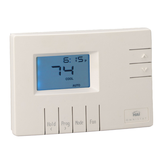
O M N I S T A T ELECTRONIC COMMUNICATING THERMOSTAT Installation Manual RC-80 Single Stage Heat/Cool Document Number 13I00-1 January, 1997... -
Page 2: Table Of Contents
CONTENTS ........DESCRIPTION ........INSTALLATION . -
Page 3: Description
DESCRIPTION The RC-80 is a precision digital thermostat designed for 24 VAC single stage heating and cooling systems. It has the capability of being controlled both locally and by remote control. It offers programmability, stand alone operation, and robust, optically isolated communications with automation systems, utility control systems, and personal computers. -
Page 4: Location
LOCATION When replacing an existing thermostat, install the RC-80 in the same location. If the existing location doesn't meet the following criteria, choose a new location to mount the RC-80. When choosing a location for the thermostat: 1. Ensure that the thermostat is mounted about 5 feet above the floor and is at least 2 feet from an outdoor wall. -
Page 5: Mounting
MOUNTING When mounting the RC-80, grasp the thermostat by the sides, avoiding the keys, and unsnap the base from the face. Holding the base to the wall so that the word "TOP" is upright and facing you: 1. Mark the two mounting holes on the wall using a pencil. 2. - Page 6 Connect each wire to the terminal strip on the thermostat base per the wiring diagram for your system application - See Figures 4 - 8. Form the thermostat wiring so that the cable lies flat between the terminal strip and the center of the thermostat base - See Figure 2. Figure 2 - Forming thermostat wiring If a remote system is being used with the thermostat, connect the...
- Page 7 Align the tabs of the thermostat face with the slots of the thermostat base. Gently push the thermostat face into the thermostat base locking it into place - See Figure 3. SLOT FACE TEMPERATURE BASE WALL SENSOR Figure 3 - Mounting thermostat face to thermostat base Note: Be sure that the thermostat temperature sensor is standing up, and...
-
Page 8: Typical Wiring Diagrams
TYPICAL WIRING DIAGRAMS CAUTION 1. Be sure to disconnect the power to the control transformer before removing or installing thermostat. 2. Do not short gas valve, fan, heat relay, or cool relay... even momentarily. This will blow a non-replaceable fuse. 3. - Page 9 24VAC CONTROL TRANSFORMER RELAY (IF USED) HEAT RELAY (OR GAS VALVE) COMMON Figure 5 - Single stage heat only thermostat 24VAC CONTROL TRANSFORMER RELAY COOL RELAY COMMON Figure 6 - Single stage cool only thermostat...
- Page 10 24VAC CONTROL TRANSFORMER RELAY COOL RELAY HEAT RELAY COMMON Common wire is not required in most heat/cool installations. Use only if heat, cool, or fan relay cannot supply 15mA to power thermostat, without activating. Figure 7 - Single stage heat/cool thermostat 24VAC (RC) CONTROL TRANSFORMER...
-
Page 11: Power Up
POWER UP 1. Double check wiring, be sure that there are no stray wires or wire strands at the connections. 2. It is not necessary to connect the remote system (COMM) cable at this time. 3. Connect power to the control transformer and system. The display will show all segments for about 5 seconds. -
Page 12: Installer Setup
INSTALLER SETUP This section describes the items that the installer must setup as part of the thermostat installation. The Installer Setup mode is used to configure the general operating parameters of the thermostat. When in Installer Setup mode: 1. The small digits on the top of the display are the item number. 2. -
Page 13: Address
00 Address If you are using Communications Mode 0 or 1, and you are installing more than one thermostat, each must be set to a consecutive address, starting at 1. The default address setting is 1. An address from 1- 127 may be selected. 01 Communications mode The thermostat can communicate with remote systems in 4 different modes. -
Page 14: Display Options
03 Display options The thermostat can be configured to display the following attributes: 0 Celsius am/pm time format programmable 1 Fahrenheit am/pm time format programmable 2 Celsius 24 hour time format programmable 3 Fahrenheit 24 hour time format programmable 4 Celsius am/pm time format non-programmable 5 Fahrenheit... -
Page 15: Heat Setpoint Limit
06 Heat setpoint limit This item is used to limit the temperature setting in heat mode. The desired heat setting can never be set above this setting. The default setting is 91. 07 Not used 08 Not used 09 Cooling anticipator This item adjusts the tendency of the thermostat to run the cooling system to refresh and dehumidify the air before the temperature rises to the desired cool setting. -
Page 16: Cooling Minimum On/Off Time
The following settings are recommended: Forced air systems Radiant systems A lower setting will decrease the tendency to turn off the heating system before the desired heat setting is reached. If the heating system response time is slower, as are most radiant heating systems, a higher number will help maintain an even space temperature. -
Page 17: Owner's Manual
(1 = - 29 to 59 = + 29 - Seconds per day - 30 = No change) The default setting is 30. Note: If an HAI automation system is being used, the controller system time is sent to the thermostat every minute. This adjustment will have no effect. -
Page 18: Quick Reference Setup Guide
QUICK-REFERENCE SETUP GUIDE This table displays each Installer Setup item with it's default setting. The column labeled "CURRENT" can be used to write down the current settings if any changes are made to the default settings. Item Number Description Default Current Address Communication mode System options... -
Page 19: Remote System Wiring Diagrams
Run a 3 (or 4) conductor wire from the HAI system to the thermostat location. All thermostats on an Omni, OmniPro, or Aegis controller are connected to Zone 16 and Output 8. - Page 20 Additional thermostats are connected in parallel. They may be connected in home-run or daisy chain configuration. REMOTE DAY/NIGHT SETBACK SWITCHES The thermostat can be connected to a remote system or remote switch. A signal can be sent from the remote location to change the thermostat temperature settings from the "DAY"...
-
Page 21: Troubleshooting Tips
TROUBLESHOOTING TIPS SYMPTOM ACTION TO TAKE Thermostat Dead 1. Check power to the thermostat 2. Check wiring diagrams 3. Check thermostat temperature sensor Thermostat will not operate with a damaged temperature sensor SYMPTOM ACTION TO TAKE Fan, Heat, Or Cool 1. - Page 22 SYMPTOM ACTION TO TAKE Temperature 1. Allow 30 minutes for thermostat to Reading Incorrect adjust to room temperature 2. Adjust calibration offset 3. Change setup option to display F or After installation, allow the thermostat up to 30 minutes for an accurate temperature reading SYMPTOM ACTION TO TAKE...
Need help?
Do you have a question about the RC-80 Omnistat and is the answer not in the manual?
Questions and answers