Table of Contents
Advertisement
Quick Links
Download this manual
See also:
Owner's Manual
3 Stage Heat / 2 Stage Cool - With Energy Efficient Control
APPLICATION
This RC-112 thermostat is applicable to heat pumps with two stages of heating and cooling, plus a third stage of
heating called "auxiliary" heating. The heat pump may have a two-speed compressor (low and high speeds), two
compressors (stage 1 and stage 2) or a "superheater" or other device as the second stage. In normal operation,
stage 1 and 2 (or low and high speed) will be used as required to maintain the set temperature. In heating mode,
the auxiliary heating will only be used if the heat pump cannot maintain a rate of temperature rise with both
stages running (high speed).
The RC-112 is capable of being controlled both locally and by remote control. It offers programmability, stand-
alone operation, and robust, optically isolated communications with automation systems, utility control systems,
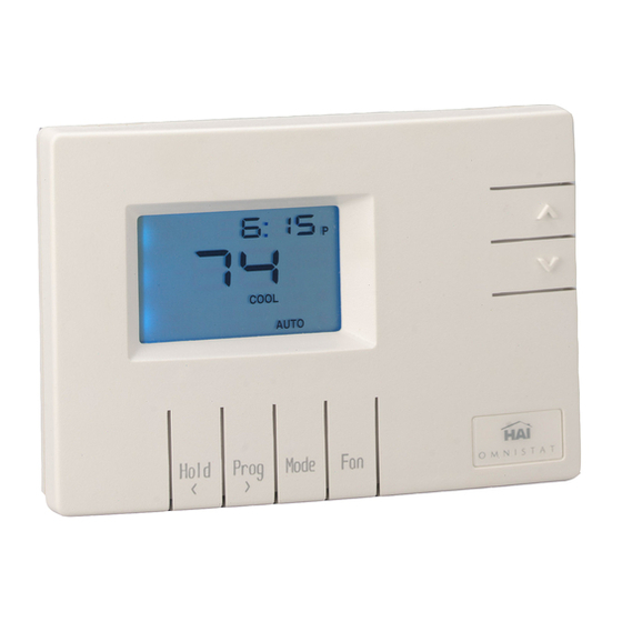
and personal computers. The RC-112B is equipped with a "cool blue" backlight display.
Electrical rating:
Maximum current:
Thermostat operating current:
The following requirements must be observed for installation in Europe: CE
1. This equipment must be installed in accordance with National wiring rules for the country in which it is
installed.
2. Fuses must be replaced only with IEC rated components.
3. All product labels, instructions and markings relating to safety must be translated to a language, which is
acceptable in the country in which this equipment is to be installed.
INSTALLATION
Before installing this thermostat:
1. Read all of the installation instructions carefully.
2. Read the Owner's Manual carefully.
3. Ensure that this product is suitable for your application.
4. Ensure that wiring complies with all codes and ordinances.
5. Disconnect power to the control transformer to prevent electrical shock and damage to equipment.
6. Select an appropriate location to ensure an accurate temperature reading.
Location
When replacing an existing thermostat, install the RC-112 in the same location. If the existing location doesn't
meet the following criteria, choose a new location. When choosing a location for the thermostat:
RC-112 / RC-112B Two Speed Heat Pump
Thermostat Installation Instructions
24 V; 3 A; 50/60 Hz
2 A on any circuit, 3 A total
less than 15 mA
Document Number 13I00-5 / Rev B / May, 2004
Copyright
1999-2004 Home Automation, Inc.
©
All Rights Reserved
1
1
Advertisement
Table of Contents

Related Manuals for HAI RC-112


Summary of Contents for HAI RC-112
- Page 1 Thermostat Installation Instructions APPLICATION This RC-112 thermostat is applicable to heat pumps with two stages of heating and cooling, plus a third stage of heating called "auxiliary" heating. The heat pump may have a two-speed compressor (low and high speeds), two compressors (stage 1 and stage 2) or a "superheater"...
- Page 2 4. Remove the existing plate or base from the wall. MOUNTING When mounting the RC-112, grasp the thermostat by the sides, avoiding the keys, and unsnap the base. Holding the base to the wall so that the word "TOP" is upright and facing you: 1.
- Page 3 Connect each wire to the terminal strip on the thermostat base per the wiring diagram for your system application - See Figures 4 - 5. Form the thermostat wiring so that the cable lies flat between the terminal strip and the center of the base. If a remote system is being used with the thermostat, connect the remote system wiring to the supplied cable using the wire splices per the diagram for your remote system application - See Figures 7 - 8.
- Page 4 The RC-112 automatically controls auxiliary heat efficiently. The RC-112 requires at least 1 stage of auxiliary heat enabled at all times. If the heat pump is equipped with an outdoor thermostat, it should be removed from the auxiliary heat circuit, or reconfigured so that it...
- Page 5 Figure 5...
- Page 6 CONFIGURING THE BACKLIGHT ON THE RC-112B The backlight on the RC-112B can be configured to one of three different modes: 1) on for 30 seconds when a key is pressed, 2) always on, or 3) always off. To configure the display backlight to turn on when a key is pressed, then back off 30 seconds later, set the “JP2”...
- Page 7 POWER UP 1. Double check wiring, be sure that there are no stray wires or wire strands at the connections. 2. It is not necessary to connect the remote system (COMM) cable at this time. 3. Connect power to the transformer and system. The display will show all segments for about 5 seconds. 4.
-
Page 8: Address
Address If you are using Communications Mode 0 or 1, and you are installing more than one thermostat, each must be set to a consecutive address, starting at 1. The default address setting is 1. An address from 1- 127 may be selected. Communications mode The thermostat can communicate with remote systems in 4 different modes. -
Page 9: Display Options
Fahrenheit 24-hour time format non-programmable When connected to an HAI controller, the thermostat should be configured as "non-programmable". To disable the clock and filter reminder displays, add “16” to each value. The default setting is 1. Calibration offset This item is used to raise or lower the current temperature reading by 1 degree Fahrenheit or 1/2 degree Celsius. -
Page 10: Stage 2 Differential
Stage 2 differential This item specifies the temperature difference between stage 1 (or low speed) heat pump operation and stage 2 (or high speed) heat pump operation. The default setting of 1 (degree F) is recommended for most applications. If energy efficiency is more important than precise temperature control, this can be raised to 2 or 3 degrees. This setting affects stage 2 operation for both heating and cooling. -
Page 11: Clock Adjust
(1 = “- 29” to 59 = “+ 29” seconds per day; 30 = No change) The default setting is 30. Note: If an HAI automation system is being used, the controller system time is sent to the thermostat every minute. This adjustment will have no effect. -
Page 12: Table Of Contents
Run a 3 (or 4) conductor wire from the HAI system to the thermostat location. All thermostats on an Omni, Omni II, OmniPro, or OmniPro II controller are connected to Zone 16 and Output 8. - Page 13 Note: Do not connect the red COMM cable wire to 12V. Figure 7 - Hookup to an HAI system Additional thermostats are connected in parallel. They may be connected in home-run or daisy chain configuration. REMOTE DAY/NIGHT SETBACK SWITCHES The thermostat can be connected to a remote system or remote switch. A signal can be sent from the remote location to change the thermostat temperature settings from the "DAY"...
- Page 14 * Red and yellow wires are not used. Insulate each using a small piece of tape. Figure 8 - Hookup to remote Day/Night setback switch OTHER SYSTEMS For connections to personal computers, utility management systems, and other automation systems, refer to connection diagrams provided with personal computer software package or other system.
- Page 15 TROUBLESHOOTING TIPS SYMPTOM ACTION TO TAKE Thermostat Dead Check power to the thermostat Check wiring diagrams Check thermostat temperature sensor Thermostat will not operate with a damaged temperature sensor SYMPTOM ACTION TO TAKE Fan, Heat, Or Cool Check for break in G, W, or Y wire Inoperative Allow minimum off time to pass Check system options for correct settings...
- Page 16 See if heat pump is equipped with outdoor thermostat. If so, Heat disconnect it. Heat pump may be equipped with an outdoor thermostat which is overriding Aux Heat when outdoor temperature is above certain level - Disconnect the outdoor thermostat, the RC-112 controls the Aux Heat automatically...
Need help?
Do you have a question about the RC-112 and is the answer not in the manual?
Questions and answers