HAI RC-1000 Installation Instructions Manual
Hide thumbs
Also See for RC-1000:
- User manual (20 pages) ,
- User manual (20 pages) ,
- Protocol manual (18 pages)
Advertisement
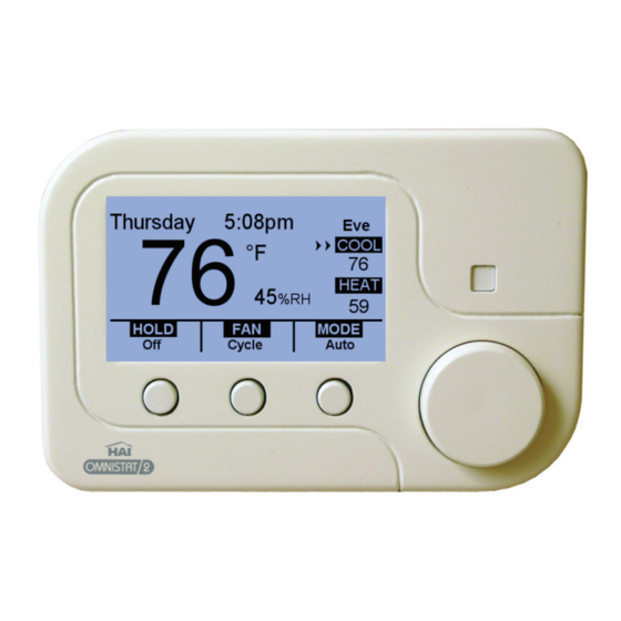
DESCRIPTION
The RC-1000 is a precision digital thermostat designed for 24 VAC heating and cooling systems.
The RC-1000 will support the following systems:
Single Stage Heat/Cool Conventional
Heat Pump (2 Stage Heat / 1 Stage Cool)
Dual Fuel Heat Pump (2 Stage Heat / 1 Stage Cool)
The RC-1000 has the capability of being controlled both locally and by remote control.
programmability, stand-alone operation, and robust, optically isolated communications with automation
systems, utility control systems, and personal computers.
Electrical rating: 24 V; 2 A; 50/60 Hz
Maximum current: 2 A on any circuit, 3 A total
The following requirements must be observed for installation in Europe:
1. This equipment must be installed in accordance with National wiring rules for the country in which it is
installed.
2. All product labels, instructions and markings relating to safety must be translated to a language, which is
acceptable in the country in which this equipment is to be installed.
INSTALLATION
Before installing this thermostat:
1. Read all of the Installation Instructions carefully.
2. Read the Owner's Manual carefully.
3. Ensure that this product is suitable for your application.
4. Ensure that wiring complies with all codes and ordinances.
5. Disconnect power to the control transformer to prevent electrical shock and damage to equipment.
6. Select an appropriate location to ensure an accurate temperature reading.
RC-1000 Thermostat Installation Instructions
Document Number 65I00-1 / Rev B / February, 2010
Copyright 2008-2010 Home Automation, Inc.
All Rights Reserved
CE
It offers
1
1
Advertisement
Table of Contents

Related Manuals for HAI RC-1000


Summary of Contents for HAI RC-1000
- Page 1 RC-1000 Thermostat Installation Instructions DESCRIPTION The RC-1000 is a precision digital thermostat designed for 24 VAC heating and cooling systems. The RC-1000 will support the following systems: Single Stage Heat/Cool Conventional Heat Pump (2 Stage Heat / 1 Stage Cool) ...
- Page 2 Location When replacing an existing thermostat, install the RC-1000 in the same location. If the existing location doesn't meet the following criteria, choose a new location to mount the RC-1000. When choosing a location for the thermostat: 1. Ensure that the thermostat is mounted 5 feet above the floor and is at least 2 feet from an outdoor wall.
- Page 3 Connect each wire to the terminal strip(s) on the thermostat base per the wiring diagram for your system application - See Figures 4 - 7. Form the thermostat wiring so that the cable lies flat between the terminal strip(s) and the center of the base - See Figure 2. If a remote system or temperature sensor is being used with the thermostat, connect the remote system or temperature sensor wiring per the diagram for the application - See Figures 8 - 11.
-
Page 4: Typical Wiring Diagrams
Terminal 1 (RC) and Terminal 2 (RH) on the left terminal strip must remain in place – See Figure 4. From the factory, the RC-1000 is configured to control a single stage conventional HVAC system. If the HVAC system is a heat pump or dual fuel heat pump, before operating the thermostat, the... - Page 5 When configured as a conventional thermostat, by default this thermostat does not turn the fan on with a call for heat. If the furnace requires the thermostat to turn the fan on with a call for heat, configure the “System Mode” to “Fan On With Heat” under “System Options”. A conventional thermostat can be configured for automatic changeover heat/cool, manual changeover heat/cool, heat only, or cool only thermostat.
-
Page 6: Hvac System
The RC-1000 thermostat is designed to work with most single state conventional 4-wire HVAC systems (without a transformer common). However, if the RC-1000 “resets” when calling for heat or cool, or if the heat, cool, or fan relay cannot supply 15mA to power thermostat without the relay activating, the transformer... - Page 7 RC-1000 can obtain the outdoor temperature from a remote system. If the RC-1000 can not obtain the outdoor temperature, the heat pump compressor will not operate and the thermostat will only call for the auxiliary heat until the problem is resolved. When this occurs, the display will flash red and the “Problem With Outdoor Temperature Sensor.
- Page 8 Heat Pump (2 Stage Heat / 1 Stage Cool) HVAC SYSTEM Fault Relay Ground Fault Fan Relay Compressor (Y1) Compressor Relay Energized in Heat Energized in Cool Reversing Valve Auxilirary Heat (W2) Aux Heat Relay 24VAC Common (RC) 24VAC "HOT" 24VAC CONTROL THERMOSTAT...
- Page 9 REMOTE SYSTEM WIRING DIAGRAMS This thermostat has been preprogrammed with energy saving program schedules. When used with a remote system, HAI recommends that the Program Mode be configured as “None” or “Occupancy”. This will disable the internal program schedules. SETTING THE COMMUNICATIONS JUMPER This thermostat comes from the factory with the communications jumper (J8) labeled “COMM JUMPER”...
- Page 10 HAI HOME CONTROL SYSTEMS The thermostat can be connected to an HAI Home Control system. The controller can send commands to the thermostat to change mode, cool setting, heat setting, status of fan and hold, and other items. Run a 3 (or 4) conductor wire from the HAI system to the thermostat location. All thermostats on an HAI Home Control system are connected to Ground, Zone +16, and Output 8 - See Figure 9.
-
Page 11: Vdc Output
REMOTE SETBACK SWITCH The thermostat can be connected to a remote switch to toggle the desired heat and cool temperature settings between preset setpoints. A signal can be sent from the remote switch location to change the thermostat temperature settings from the Occupancy Day temperature settings to the Occupancy Night temperature settings. -
Page 12: Remote Temperature Sensor
Run a twisted pair, shielded cable from the RC-1000 to the remote temperature sensor location. For distances up to 100 feet, typical twisted pair, PVC-insulated, shielded cable may be used. For distances from 100-150 feet, twisted pair with polypropylene insulated conductors, shielded must be used. - Page 13 DISABLE LOCAL CONTROL The Task Buttons and Scroll Wheel on the thermostat can be disabled to prevent anyone from controlling the thermostat locally. To disable the Task Buttons and Scroll Wheel: Remove the thermostat face from the thermostat base. Remove the local control jumper - See Figure 12. Align the tabs of the thermostat face with the slots of the thermostat base.
-
Page 14: Setup And Configuration
SETUP AND CONFIGURATION NOTE: For proper operation of the features of this thermostat, the Time and Date must be set. Even when connected to an HAI controller which sets the time and day, the Date must be manually set in the thermostat under the “Settings” menu. INSTALLATION SETTINGS This section describes the items that the installer must setup as part of the thermostat installation. - Page 15 System Options Note: Before operating the thermostat, the “System Type” and “System Mode” must be configured. The thermostat can be configured with the following system options: *Conventional Dual Fuel Heat Pump Heat Pump System Type *Auto Changeover Auto Changeover Auto Changeover Manual Changeover Manual Changeover Manual Changeover...
- Page 16 Stage Settings When configured as a heat pump thermostat, by default the RC-1000 is configures for two states of heat (auxiliary heat is included in this number). If the heat pump is not equipped with auxiliary heat, the Heat Stages setting may be set to one (in this configuration, auxiliary will never be used).
- Page 17 Auxiliary Heat Differential: This determines how far from the setpoint the temperature has to be before the auxiliary heat turns on. This is only available for heat pump systems. Start Delay (Minutes): This item sets the minimum amount of time the heating system must run before the Auxiliary Heat Stage is used.
- Page 18 Temperature Sensors The Temperature Sensor settings are used to configure the internal temperature sensor and an optional remote temperature sensor that is connected to the thermostat. When the internal sensor is enabled and the external sensor is set to “Indoor”, the displayed temperature will be the average temperature of the two sensors. Internal Sensor: This will enable or disable the onboard temperature sensor for indoor use only.
-
Page 19: Troubleshooting Tips
TROUBLESHOOTING TIPS SYMPTOM ACTION TO TAKE Thermostat Dead Check power to the thermostat Check wiring diagrams SYMPTOM ACTION TO TAKE Heat Or Cool Inoperative Check for break in W or Y wire Allow minimum off time to pass Check system options for correct settings If arrow is blinking, wait until startup delay expires Mode is Off (Select Heat, Cool, or Auto) Remote system is overriding thermostat... -
Page 20: Limited Warranty
LIMITED WARRANTY HAI warrants this product against defects in material and workmanship, under normal use and service, for a period of two (2) years from the date of purchase. During the warranty period, HAI will repair or replace, at its sole option, if this product fails due to defect.
Need help?
Do you have a question about the RC-1000 and is the answer not in the manual?
Questions and answers