Table of Contents
Advertisement
Quick Links
DESCRIPTION
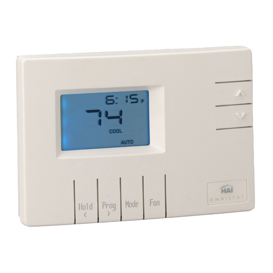
The RC-90 is a precision digital thermostat designed for 24 VAC single stage heating and cooling systems. It
has the capability of being controlled both locally and by remote control. It offers programmability, stand-alone
operation, and robust, optically isolated communications with automation systems, utility control systems, and
personal computers. The RC-90B is equipped with a "cool blue" backlight display.
Electrical rating:
Maximum current:
Thermostat operating current:
The following requirements must be observed for installation in Europe: CE
1. This equipment must be installed in accordance with National wiring rules for the country in which it is
installed.
2. Fuses must be replaced only with IEC rated components.
3. All product labels, instructions and markings relating to safety must be translated to a language, which is
acceptable in the country in which this equipment is to be installed.
INSTALLATION
Before installing this thermostat:
1. Read all of the installation instructions carefully. Read the Owner's Manual carefully.
2. Ensure that this product is suitable for your application.
3. Ensure that wiring complies with all codes and ordinances.
4. Disconnect power to the control transformer to prevent electrical shock and damage to equipment.
5. Select an appropriate location to ensure an accurate temperature reading.
Location
When replacing an existing thermostat, install the RC-90 in the same location. If the existing location doesn't
meet the following criteria, choose a new location to mount the RC-90. When choosing a location for the
thermostat:
1. Ensure that the thermostat is mounted 5 feet above the floor and is at least 2 feet from an outdoor wall.
2. Ensure that the thermostat is located in an area where there is adequate air circulation.
3. Do not mount in the path of direct sunlight or of radiant heat generated by appliances.
4. Do not mount behind an outdoor wall, near a fireplace, or in the path of any air ducts.
RC-90 / RC-90B Single Stage Heat/Cool
Thermostat for Zone Control Systems
Installation Instructions
24 V; 3 A; 50/60 Hz
2 A on any circuit, 3 A total
less than 15 mA
Document Number 13I00-28 / Rev B / April, 2004
Copyright
1999-2004 Home Automation, Inc.
©
All Rights Reserved
1
1
Advertisement
Table of Contents

Related Manuals for HAI RC-90


Summary of Contents for HAI RC-90
-
Page 1: Installation Instructions
Installation Instructions DESCRIPTION The RC-90 is a precision digital thermostat designed for 24 VAC single stage heating and cooling systems. It has the capability of being controlled both locally and by remote control. It offers programmability, stand-alone operation, and robust, optically isolated communications with automation systems, utility control systems, and personal computers. - Page 2 4. Remove the existing plate or base from the wall. MOUNTING When mounting the RC-90, grasp the thermostat by the sides, avoiding the keys, and unsnap the base from the face. Holding the base to the wall so that the word "TOP" is upright and facing you: 1.
- Page 3 Connect each wire to the terminal strip on the thermostat base per the wiring diagram for your system application - See Figures 4 - 7. Form the thermostat wiring so that the cable lies flat between the terminal strip and the center of the base. If a remote system is being used with the thermostat, connect the remote system wiring to the supplied cable using the wire splices per the diagram for your remote system application - See Figures 9 - 10.
-
Page 4: Typical Wiring Diagrams
TYPICAL WIRING DIAGRAMS CAUTION: Be sure to disconnect the power to the control transformer before removing or installing thermostat. Do not short gas valve, fan, cool mode relay, heat mode relay, heat relay, or cool relay...even momentarily. This will blow a non-replaceable fuse. Do not attempt to hook up to live circuits. - Page 5 Figure 5 – Installation as a Master thermostat...
- Page 6 Figure 6 – Installation as a Slave thermostat Figure 7 - Installation as a Zone thermostat with separate transformer - Required by some zone panels...
-
Page 7: Disable Keys
NOTE ON ADDITIONAL OUTPUTS The RC-90 has two additional outputs (B and O) for use with zoned heating and cooling systems. The B and O terminals control the mode of operation (heating or cooling) of the zone control panel. The zone control panel will recognize calls for heat (W) from the individual zones when the B terminal is energized, and calls for cool (Y) when the O terminal is energized. -
Page 8: Installer Setup
TO DISABLE KEYS LOCALLY SELECT BACKLIGHT SOLDER WIRE JUMPER HERE MODE (SET JUMPER) Figure 8 INSTALLER SETUP This section describes the items that the installer must setup as part of the thermostat installation. The Installer Setup mode is used to configure the general operating parameters of the thermostat. When in Installer Setup mode: 1. - Page 9 The word "default" indicates the initial setting when the thermostat is delivered from the factory. Address If you are using Communications Mode 0 or 1, and you are installing more than one thermostat, each must be set to a consecutive address, starting at 1. The default address setting is 1. An address from 1- 127 may be selected.
- Page 10 Fahrenheit 24-hour time format non-programmable When connected to an HAI controller, the thermostat should be configured as "non-programmable". To disable the clock and filter reminder displays, add “16” to each value. The default setting is 1. Calibration offset This item is used to raise or lower the current temperature reading by 1 degree Fahrenheit or 1/2 degree Celsius.
- Page 11 Cooling anticipator This item adjusts the tendency of the thermostat to run the cooling system to refresh and dehumidify the air before the temperature rises to the desired cool setting. A setting of 0 will disable this feature. No anticipation Normal anticipation Maximum anticipation The recommended setting for most forced air cooling systems is 4.
- Page 12 (1 = “- 29” to 59 = “+ 29” seconds per day; 30 = No change) The default setting is 30. Note: If an HAI automation system is being used, the controller system time is sent to the thermostat every minute. This adjustment will have no effect.
-
Page 13: Remote System Wiring Diagrams
Run a 3 (or 4) conductor wire from the HAI system to the thermostat location. All thermostats on an Omni, Omni II, OmniPro, or OmniPro II controller are connected to Zone 16 and Output 8. - Page 14 Figure 9) using the supplied wire splices. Note: Do not connect the red COMM cable wire to 12V. Figure 9 - Hookup to an HAI system Additional thermostats are connected in parallel. They may be connected in home-run or daisy chain...
-
Page 15: Other Systems
REMOTE DAY/NIGHT SETBACK SWITCHES The thermostat can be connected to a remote system or remote switch. A signal can be sent from the remote location to change the thermostat temperature settings from the "DAY" setting to the "NIGHT" setting. To use this mode, setup item 01 - "Communications mode"... -
Page 16: Troubleshooting Tips
TROUBLESHOOTING TIPS SYMPTOM ACTION TO TAKE Thermostat Dead Check power to the thermostat Check wiring diagrams Check thermostat temperature sensor Thermostat will not operate with a damaged temperature sensor SYMPTOM ACTION TO TAKE Fan, Heat, Or Cool Check for break in G, W, or Y wire Inoperative Allow minimum off time to pass Check system options for correct settings...
Need help?
Do you have a question about the RC-90 and is the answer not in the manual?
Questions and answers