Table of Contents
Advertisement
Quick Links
Advertisement
Table of Contents

Related Manuals for Powerhouse PH4000Ri/E


Summary of Contents for Powerhouse PH4000Ri/E
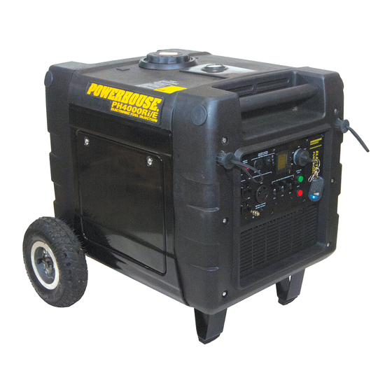
- Page 1 POWERHOUSE ® PH4000Ri/E Digital Inverter Generator SERVICE MANUAL December 2014...
-
Page 2: Preface
PREFACE ® This manual covers the construction, function and servicing procedure of the POWERHOUSE PH4000Ri/E generator, certificated by CARB. Careful observance of these instructions will result in better, safer service work. All information, illustrations, directions and specifications included in this publication are based on the latest product information available at the time of approval for printing. -
Page 3: Table Of Contents
3.15 Engine will not start or stop with remote....................30 3.15.1 Remote Switch Inspection ......................31 4. Maintenance ..............................32 4.1 Maintenance schedule..........................32 4.2 Checking the oil level ..........................33 4.3 Changing oil ............................33 4.4 Checking the Oil Level Sensor ....................... 35 PH4000Ri/E SM Revision 12-31-2014... - Page 4 7.1 Disassembly and installation ........................59 7.2 Digital Display ............................60 7.2.1 Voltage Display Field ........................60 7.2.2 Amperage and Wattage Display Fields ................... 61 7.2.3 Hour Meter ............................61 7.2.4 Fuel Level Display ..........................62 PH4000Ri/E SM Revision 12-31-2014...
- Page 5 12.3 Inspection ............................. 78 13. Crankshaft / Piston ............................. 79 13.1 Crankshaft, Camshaft and Piston ......................79 13.2 Alignment of Timing Marks ........................80 13.3 Camshaft Inspection ..........................81 13.4 Piston / Connecting rod ........................82 PH4000Ri/E SM Revision 12-31-2014...
-
Page 6: Specifications
SAE 10W-30/15W-30 (SF/SG grade or greater) for temps above 32 F; Lube oil SAE 0W-30/0W-40 for temps below 32 F Oil capacity 33.8 oz. (1.0 L) Starting system Remote, Electric, & Recoil Stopping system Electrical Fuel Cut-off Fuel used Automotive unleaded gasoline PH4000Ri/E SM Revision 12-31-2014... -
Page 7: Characteristics
DC circuit protector Fuel tank capacity 4.5 gal (17.0 L) Continuous running time 8.9 hours / 18.0 hours (at rated load / at ¼ load) 64-73 dB @ 23’ (7m) Noise level (Zero load to full load) PH4000Ri/E SM Revision 12-31-2014... -
Page 8: Wiring Diagram
1.3 Wiring Diagram PH4000Ri/E SM Revision 12-31-2014... -
Page 9: Service Information
To reduce the possibility of a fire or explosion, be careful when working around gasoline. Use only a nonflammable solvent, not gasoline, to clean parts. Keep all cigarettes, sparks and flames away from fuel and all fuel-related parts. PH4000Ri/E SM Revision 12-31-2014... -
Page 10: Service Rules
1. Use genuine POWERHOUSE or POWERHOUSE recommended parts and lubricants or their ® equivalents. Parts that do not meet POWERHOUSE design specifications may damage the engine. 2. Always install new gaskets, O-rings, etc. when reassembling. 3. When tightening bolts or nuts, begin with larger-diameter or inner bolts first and tighten to the specified torque diagonally, unless a particular sequence is specified. -
Page 11: Serial Number Location
17.95mm Piston pin O.D. (0.7084”-0.7087”) (0.7067”) 1.97-1.99mm 1.87mm Height h (0.0776”-0.0783”) (0.0736”) 0.02-0.06mm 0.15mm Ring side clearance (0.006”) (0.001”-0.002”) Piston ring 1st ring 0.15-0.25mm 1.0mm Ring end clearance (0.006”-0.010”) (0.04”) 3.40-3.60mm 3.20mm Width t (0.134”-0.142”) (0.126”) PH4000Ri/E SM Revision 12-31-2014... - Page 12 Seat width IN/EX 39.1mm (1.54”) 37.5mm (1.48”) Valve spring Free length IN/EX 31.700-31.780mm 31.0mm Cam wheel Cam height (1.2480”-1.2512”) (1.2205”) 0.6-0.7mm — Spark plug (0.024”-0.028”) 1.4-2.0 Ω — Primary side Ignition Coil Resistance — Second side 11.0-15.0kΩ PH4000Ri/E SM Revision 12-31-2014...
-
Page 13: Motor
3.11 No or low AC output 3.12 Measuring stator output voltage while running 3.13 No DC output at battery charge receptacle 3.14 Battery will not charge 3.15 Engine will not start or stop with remote, key operation normal PH4000Ri/E SM Revision 12-31-2014... -
Page 14: Battery Charge Requirements
Replace the starter relay. See section 9.3. Normal If starter fails to operate properly replace Inspect the starter motor wire and Abnormal the starter motor. See section 9.2 for connection. Test the starter motor. See details. section 9.2. PH4000Ri/E SM Revision 12-31-2014... -
Page 15: Cranks But Doesn't Start
12). Lap valves, or replace & regrind as Install the spark plug securely. Engine necessary. should now start and run. 4. Check for worn piston, piston ring or cylinder (section 13). Re-ring or overhaul as necessary. PH4000Ri/E SM Revision 12-31-2014... -
Page 16: Hard Starting (Cranks & Starts, But Is Hard To Start)
12). Lap valves, or replace & regrind as Install the spark plug securely. Engine necessary. should now start and run. 4. Check for worn piston, piston ring or cylinder (section 13). Re-ring or overhaul as necessary. PH4000Ri/E SM Revision 12-31-2014... -
Page 17: Cylinder Compression Check
3. Push the remote switch to the OFF position. 4. Turn the ignition switch to the START position and hold until the compression gauge no longer rises. Read compression. 0.45Mpa (65 psi) @ ~800rpm Cylinder compression Compression Gauge Remote Switch PH4000Ri/E SM Revision 12-31-2014... -
Page 18: Ignition System
CPS, ignition switch, and ECU for necessary. breaks, shorts, or bad connections. Normal, Still no Still no spark A problem with the wire harness has been spark overlooked. Repeat inspection of the wire Replace ECU. Spark should be restored. harness. PH4000Ri/E SM Revision 12-31-2014... -
Page 19: Checking For Spark
A healthy Ground Wire ignition system will produce a spark as shown in Fig. 8. If there is no, or a weak, spark; continue following the ignition troubleshooting flowchart. Fig. 2 Fig. 3 PH4000Ri/E SM Revision 12-31-2014... -
Page 20: Ignition Coil Inspection
If the resistance is within range through the spark plug wire, but not the wire and cap; replace the spark plug cap. 7. Replace the ignition coil if the resistance is outside of the range shown below. Secondary resistance 17.5-19.0kΩ PH4000Ri/E SM Revision 12-31-2014... -
Page 21: Ignition Switch Inspection
3-5, but failed steps 6-8 then look for a wiring problem in the ignition switch circuits. Wire Voltage at Different Switch Positions Ignition Switch Position Wire Color START Black (Gnd) (Gnd) (Gnd) (Batt+) (Batt+) (Batt+) Orange (Batt+) (Batt+) Blue (Batt+) Pink (Gnd) PH4000Ri/E SM Revision 12-31-2014... -
Page 22: Oil Level Sensor Fails To Stop Engine When Oil Is Low
(section Replace the digital display. 4.4, Fig. 13). Does the low oil light illuminate? Light comes on Spark Check for spark with the white wire Replace the ECU. grounded (section 3.6.1). No spark ECU is OK. PH4000Ri/E SM Revision 12-31-2014... -
Page 23: Engine Stops Running
Perform compression test as detailed in 3. Check the valve cone and seat (section section 3.5. 12). Lap valves, or replace & regrind as necessary. 4. Check for worn piston, piston ring or cylinder (section 13). Re-ring or overhaul as necessary. PH4000Ri/E SM Revision 12-31-2014... -
Page 24: Engine Speed Can't Increase, Is Unstable Or Is Hunting
Clean as necessary. section 3.5. 3. Check the valve cone and seat (section 12). Lap valves, or replace & regrind as necessary. 4. Check for worn piston, piston ring or cylinder (section 13). Re-ring or overhaul PH4000Ri/E SM Revision 12-31-2014 as necessary. -
Page 25: Engine Speed Too High
The ECU will draw the engine down to idling speed. The digital display will indicate zero (0) Volts. The 120 V receptacles will not supply voltage, regardless of breaker settings. Verify inverter failure (section 3.11) and replace inverter (section 10.1). PH4000Ri/E SM Revision 12-31-2014... -
Page 26: No Or Low Ac Output
Measure the stator output voltage while Abnormal Inspect and repair stator wire harness or running (see section 3.12), and the stator replace stator. See section 10.1. winding resistance (see section 10.1). Normal Replace inverter. See section 10.1. PH4000Ri/E SM Revision 12-31-2014... -
Page 27: Measuring Stator Output Voltage While Running
If the wire harness is the problem, look for and repair the damage. 3. If the stator/rotor assembly is the problem, the stator will need to be replaced. If all three tests are OK, the problem is probably the inverter. PH4000Ri/E SM Revision 12-31-2014... -
Page 28: No Dc Output At Battery Charge Receptacle
If no wiring voltage of the stator charge windings issues found, replace the stator. See (Fig. 9). Voltage: 16-20VAC section 10. Normal Replace the voltage regulator. Fig. 9 Battery Charge To the Windings Voltage from Stator Regulator PH4000Ri/E SM Revision 12-31-2014... - Page 29 Wire to Starter Relay Voltage Regulator Harness Plug to Control Panel 30A ATC Fuse To LCD Screen Harness Plug to Harness Plug to Stator Charge Chassis Harness Plug Load Controller Windings Ground to Battery Starter Relay Ground PH4000Ri/E SM Revision 12-31-2014...
-
Page 30: Engine Will Not Start Or Stop With Remote
Repair any broken or shorted wires. connections, and broken or shorted wires. Normal Replace the remote transmitters and receiver. The remote transmitter and receiver are a matched set, and are bought in pairs. They cannot be retrained. PH4000Ri/E SM Revision 12-31-2014... -
Page 31: Remote Switch Inspection
(see section 6.8). Ground from Load Controller Fig. 12 Fig. 11 12V Battery Voltage from 3-pin Control Panel To Remote Connector Receiver PH4000Ri/E SM Revision 12-31-2014... -
Page 32: Maintenance
® (3) Service should be performed by a POWERHOUSE authorized agency, unless correct tools and a professional specialist are available. Service should always be performed according to the Service Manual. -
Page 33: Checking The Oil Level
3. If the oil level is low, add oil until it reaches the edge of the upper line on the dipstick (when screwed in as shown in the picture below). 4. Re-install the dipstick and the engine oil access door before restarting your generator. Upper Limit Upper level Lower Limit Lower level PH4000Ri/E SM Revision 12-31-2014... -
Page 34: Changing Oil
Lower Limit Lower level Please dispose of used motor oil in a manner that is compatible with the environmental and local disposal regulations. Do not throw it in the trash or pour it on the ground. PH4000Ri/E SM Revision 12-31-2014... -
Page 35: Checking The Oil Level Sensor
Check Continuity Lead to the between the Oil ECU and Level Sensor Lead Lead to the Oil Digital Display and Ground Level Sensor Fig. 14 Fig. 13 PH4000Ri/E SM Revision 12-31-2014... -
Page 36: Air Cleaner
If the engine is operated in dusty areas, clean the air cleaner more often than specified in the Maintenance Schedule (section 4.1). Never run the engine if there is no element or if the filter is damaged, as it will cause serious damage to the engine. PH4000Ri/E SM Revision 12-31-2014... -
Page 37: Spark Plug
5. Install the plug finger tight to seat the washer and then tighten with a plug wrench. Torque value shown below; or ⅛ of a turn after seating with a previously compressed washer, or ¼ turn after seating with a new uncompressed washer. Torque valve is 8.0-10 ft-lbs. (11-13 Nm) PH4000Ri/E SM Revision 12-31-2014... -
Page 38: Valve Clearance
Secure the rocker arm nut and tighten the jam nut. Recheck the clearance. 5. Clean the cylinder block and valve cover. 6. Replace the rubber valve cover seal. 7. Install the removed parts in the reverse order of removal. Fig. 16 PH4000Ri/E SM Revision 12-31-2014... -
Page 39: Evaporation Control System
4.9 Fuel Filter Wait 5-10 seconds after engine shutdown prior to filter change to allow the fuel pressure to bleed off. Use only the OEM Powerhouse replacement fuel filter when servicing this generator. Replacing Fuel Filter: 1. Remove the 8 control panel screws and carefully allow the control panel to hang out of the way. -
Page 40: Muffler System
3. Remove the spark arrester. 4. Clean the spark arrestor with a stiff wire brush. 5. Replace the spark arrestor if the wire mesh is perforated or torn. 6. Reinstall the spark arrester. 7. Reinstall the exhaust grill. PH4000Ri/E SM Revision 12-31-2014... -
Page 41: Muffler Removal
6. Remove the muffler. This gains access to O sensor and exhaust fan (Fig. 19-D). Upper Frame and Gas Tank Fig. 19-A Fig. 19-B Muffler Cover Bolts Fig. 19-D Fig. 19-C Exhaust Fan Gasket Long M8x85 Spacer M8x90 Sensor Short M8x170 M8x150 Spacer PH4000Ri/E SM Revision 12-31-2014... -
Page 42: Electronic Fuel Injection (Efi)
EFI system sensor or component. The components of the EFI system are shown in the diagram below. Their functions, maintenance and service are detailed in the sections that follow. Sensor Ignition Coil Temperature Crankshaft Fuel Injector Sensor Position Throttle Body Sensor Step Motor MAP Sensor Load Controller PH4000Ri/E SM Revision 12-31-2014... -
Page 43: Engine Control Unit (Ecu)
2. The ECU is located in the upper right hand corner of the space behind the control panel (Fig. 20). Remove the two ECU mounting screws. 3. Disconnect the 18-pin connector and remove the ECU. 4. Install in reverse order of removal. Fig. 20 PH4000Ri/E SM Revision 12-31-2014... -
Page 44: Fault Codes
The key must then be turned off to complete the process. Fault Code Reset Button Data Fields Low Oil Indicator (red) / Fault Code Indicator Sample Fault Code PH4000Ri/E SM Revision 12-31-2014... -
Page 45: Fault Code Definition And Descriptions
Step Motor P0505 Malfunction Signal line short to ground Signal line break Signal line short to battery Fault Code FCI Control Circuit voltage P0650 Indicator Light Malfunction Signal line short to ground Signal line break PH4000Ri/E SM Revision 12-31-2014... -
Page 46: Manifold Air Pressure Sensor (Map)
1VDC. If it is reading no voltage, or the voltage fails to change, or it is getting readings that are grossly off, then the MAP sensor needs to be replaced. Atmospheric Pressure = 101.3kPa, 14.7psi, or 0.0 in-Hg vacuum 1 psi = 6.9kPa 1 in-Hg = 3.4kPa PH4000Ri/E SM Revision 12-31-2014... -
Page 47: Oxygen Sensor (O )
O sensor (see section 6.5.2). 6. If the O sensor passed the output test, reconnect it and clear the ECU of any fault codes that may have been generated during the test (refer to section 6.3). PH4000Ri/E SM Revision 12-31-2014... -
Page 48: Replacing The O 2 Sensor
4. Install the new O sensor in the exhaust manifold. Torque to 13-15 ft-lbs (18-20 N·m), or tighten ⅛-¼ turn after seating washer. 5. Install the items removed in reverse order of removal. Fig. 23 Fig. 22 PH4000Ri/E SM Revision 12-31-2014... -
Page 49: Temperature Sensor
7. Re-install the temperature sensor making sure to clean all contact surfaces between the mounting bolt and the cylinder head for good heat transfer. Re-install the control panel and the maintenance door. Temperature Sensor Dimensions in mm PH4000Ri/E SM Revision 12-31-2014... -
Page 50: Crankshaft Position Sensor (Cps)
4. Rotate the rotor to make sure there is no interference with any other rotor components. 5. Re-assemble in the reverse order of disassembly. 1.0-1.2mm (0.040”-0.050”) CPS sensor clearance Fig. 27 TDC Block Rotor Crankshaft Position Sensor Feeler Gauge PH4000Ri/E SM Revision 12-31-2014... -
Page 51: Load Controller
3. If grounding the blue wire causes 12VDC to appear in the red wire with the black stripe then the fuel pump relay is working properly; proceed to step 6. PH4000Ri/E SM Revision 12-31-2014... -
Page 52: Overload Reset Button Test
3. If the switch, wiring and load controller have all been verified as good components or replaced and the inverter still fails to reset, replace the inverter. To Load Fig. 33 Controller PH4000Ri/E SM Revision 12-31-2014... -
Page 53: Fuel Injector
37 and 38). Clean out any obstructions or debris using compressed air. Apply a thin film of motor oil or assembly lube on the upper fuel injector O-ring and reinstall the injector cap. Fig. 37 Fig. 38 PH4000Ri/E SM Revision 12-31-2014... - Page 54 Reinstall the fuel injector, ECU, control panel and maintenance cover. Apply a thin film of motor oil or assembly lube on the lower fuel injector O-ring before inserting it in its mounting hole. Fuel Injector Pulse Tester PH4000Ri/E SM Revision 12-31-2014...
-
Page 55: Fuel Pump
6.10 Fuel Pump The PH4000Ri/E is equipped with an electric fuel pump mounted inside the fuel tank next to the filler neck (Fig. 43). The fuel pump needs to maintain 25psi in the system for proper operation of the fuel injector. -
Page 56: Replacing And Servicing The Fuel Pump
4 of the fuel pump test section 6.10 to verify normal operation has been restored before continuing. 10. Install the new or repaired fuel pump assembly in the reverse order of removal. Fig. 48 Fig. 49 Pressure Relief Valve Fuel Pump Tube Fuel Pump Filter PH4000Ri/E SM Revision 12-31-2014... -
Page 57: Intake Manifold
7. Remove the two nuts from the intake manifold studs and remove the air cleaner. 8. Remove the fuel injector bolt and the fuel injector. 9. Disconnect the step motor connector. 10. Remove the intake manifold (circled below) by sliding it off its studs. PH4000Ri/E SM Revision 12-31-2014... -
Page 58: Throttle Control - Step Motor
1. Measure the resistance of the outlet terminals of the step motor. Pin 1-blue - Pin 2-white:50-55Ω Resistance value Pin 3-red - Pin 4-black:50-55Ω 2. Replace the step motor if the resistance exceeds the standard values. Fig. 52 PH4000Ri/E SM Revision 12-31-2014... -
Page 59: Control Panel
Remove 8 Mounting Screws 12V DC Circuit Breaker Ignition Switch Ignition Key LCD Digital Display 120V-20 & 30 amp Circuit Breakers 120V 20amp Duplex (5-20) Overload and 120V 30amp Stop Buttons (L5-30) Grounding Remote 12V Receptacle Switch PH4000Ri/E SM Revision 12-31-2014... -
Page 60: Digital Display
30A breakers. If there is no continuity or there is resistance in these wires inspect them for breaks, shorts or bad connections. Replace or repair the wires as necessary. If there are no wiring issues found, or fixing the wiring issues has not restored proper voltage display, then replace the digital display. PH4000Ri/E SM Revision 12-31-2014... -
Page 61: Amperage And Wattage Display Fields
If the display passes steps 1-3 but the hour meter fails to begin recording time after 0.1hrs (6 min.) has passed, then replace the digital display. PH4000Ri/E SM Revision 12-31-2014... -
Page 62: Fuel Level Display
It should be noted that on the first production runs of the PH4000Ri/E the fuel level display will only indicate the fuel level while the generator is running. If the key is in the ON position, but the engine is not running, the display will indicate the battery voltage in the 0-5 bar scale. -
Page 63: Low Oil Indicator Light
0Ω. 4. Once it has been verified that there are no wiring issues, if the Fault Code Reset Button still fails to work, replace the digital display. PH4000Ri/E SM Revision 12-31-2014... -
Page 64: Outer Generator Housing
Handles Rear Cover Handle Sponge Carbon Canister Exhaust Grill Inverter Oil Access Cover Right Cover Starter Relay DC Voltage Regulator Load Controller Battery Left Cover Handle Sponge Front Cover Wheels Control Panel Maintenance Cover Rubber Feet PH4000Ri/E SM Revision 12-31-2014... -
Page 65: Recoil Starter Disassembly And Reassembly
6. Remove inverter bolts and gently lay the inverter on its back (Fig. 56). 7. Remove the three M6 flange bolts (circled in Fig. 56) and remove the recoil starter. 8. Reinstall all components in reverse order. Fig. 55 Recoil Starter Inverter Fig. 56 Recoil Starter Inverter PH4000Ri/E SM Revision 12-31-2014... -
Page 66: Intake Fan Cover
6. Disconnect the starter motor wire and all ground wires. Remove 4 nuts from the engine mounting bolts (2 on each side) and lift the engine assembly off the base pan. Upper Frame and Gas Tank Fig. 57 Fig. 58 Fig. 59 Mounting Bolts PH4000Ri/E SM Revision 12-31-2014... -
Page 67: Starter Motor
START position and verify that the starter performs as well as it did in step 3. If not, check the cable from the starter relay for breaks, shorts or bad connections. See section 3.2 if there are further problems. Cable from Starter Relay Fig. 61 Starter Motor PH4000Ri/E SM Revision 12-31-2014... -
Page 68: Removal And Replacement
(see section 10). 7. Replace the starter using these steps in reverse order. Fig. 62 Fig. 63 M6 Intake Fan Cover Bolts Cable from Starter Relay M8 Starter Motor Bolts #2 Phillips Screws PH4000Ri/E SM Revision 12-31-2014... -
Page 69: Starter Relay
If good power is being supplied by the relay to the starter but the starter fails to operate properly see section 9.2 for starter service. Battery Cable from Terminal Starter Starter Relay Fig. 65 motor Fig. 66 Terminal Start Wire from Starter Motor Ignition Switch Chassis Ground PH4000Ri/E SM Revision 12-31-2014... -
Page 70: Bench Testing The Starter Relay
There must only be continuity between the battery and starter terminals when the relay is activated. Checking Resistance Fig. 67 Checking Continuity Fig. 68 Connect to 12V positive battery terminal Connect to negative battery terminal PH4000Ri/E SM Revision 12-31-2014... -
Page 71: Stator And Rotor Disassembly And Reassembly
Main windings Measure the resistance between each of the main winding terminals at the 6-pin connector (Fig. 69). Black-Black-Black Resistance 0.25-0.35 Ω Fig. 69 2-Pin Connector from Stator to Voltage Regulator 6-Pin Connector from Stator to Inverter PH4000Ri/E SM Revision 12-31-2014... - Page 72 12. Remove the cable retainer clip and 4 stator mounting bolts using a M5 Allen wrench (Fig. 72). 13. Reverse the procedure to reassemble. Rotor Fig. 70 Stator Stator Rotor Nut Bolts Intake fan Starter Cup Crankshaft Position Sensor Fig. 72 Fig. 71 M6X1 Bolts Cable Retainer Clip and Bolt PH4000Ri/E SM Revision 12-31-2014...
-
Page 73: Exploded Engine View
11. Exploded Engine View PH4000Ri/E SM Revision 12-31-2014... - Page 74 03050626 Exhaust Manifold Stud 09080534 69558 Guide Plate 09070376-1 62475 Valve Adjusting Stud 09080525 69562 Rocker Arm 09080524 62479 Adjustment Nut 09074014 69569 Valve Adjusting Jam Nut 09080521 69568 Valve Spring Washer 09080519 69561 Valve Spring PH4000Ri/E SM Revision 12-31-2014...
- Page 75 Exhaust Valve Spring Cup, Top 09080526 Valve Adjustment Spacer 09080151 69537 Spark Plug, F7RTC 03050295 62489 Cylinder Head Bolt 09080508 60554 Valve Cover Gasket 09080533 69265 Valve Cover 09070429 69263 Seal, Valve Cover 03030168 Washer 03050628 62590 Valve Cover Bolt PH4000Ri/E SM Revision 12-31-2014...
-
Page 76: Cylinder Head / Valves
8. Remove the upper and lower engine covers (Fig. 76). 9. Remove the valve cover and 4 - M10 head bolts. Muffler Cover Muffler Case Fig. 73 Fig. 74 Muffler Fig. 75 Fig. 76 Upper Engine cover Exhaust Manifold Lower Engine Exhaust Fan cover PH4000Ri/E SM Revision 12-31-2014... -
Page 77: Cylinder Head Disassembly And Reassembly
Valve Cover Bolt Breather Tube Head Gasket and Rubber Seal 12.2 Cylinder Head Disassembly and Reassembly Valve Guide Exhaust Valve Tappet Valve Spring Intake Valve Rocker Valve spring Retainer Rocker arm Push Stud Lock Nut Rocker Arm Pivot PH4000Ri/E SM Revision 12-31-2014... -
Page 78: Inspection
Service limit 39.1mm (1.54”) 37.5mm (1.48”) ● Valve seat width Standard Service limit 0.8mm (0.03”) 1.8mm (0.07”) ● Valve stem outer diameter Standard Service limit 6.465-6.480mm (0.2545”-0.2551”) 6.40mm (0.2520”) Inlet valve 6.455-6.470mm (0.2541”-0.2547”) 6.40mm (0.2520”) Exhaust valve PH4000Ri/E SM Revision 12-31-2014... -
Page 79: Crankshaft / Piston
13. Crankshaft / Piston 13.1 Crankshaft, Camshaft and Piston Piston and Rod Front Engine Seal Front Crankshaft Lifters Bearing Low Oil Sensor Crankshaft Rod Bolts Lower Rod Cap PH4000Ri/E SM Revision 12-31-2014... -
Page 80: Alignment Of Timing Marks
13.2 Alignment of Timing Marks Use marks to align camshaft gear and timing gear during installation. Fig. 77 Timing Marks Cam Gear Crankshaft Gear Fig. 78 PH4000Ri/E SM Revision 12-31-2014... -
Page 81: Camshaft Inspection
13.3 Camshaft Inspection ● Height of camshaft Standard Service limit 31.700-31.780mm (1.2480”-1.2512”) 31.0mm (1.2205”) Intake/Exhaust PH4000Ri/E SM Revision 12-31-2014... -
Page 82: Piston / Connecting Rod
Make sure the 1st ring and 2nd ring are not interchanged. Oil ring Make sure the piston rings are free to move after installation. Stagger each piston ring gap 120° from each of the other rings. PH4000Ri/E SM Revision 12-31-2014... - Page 83 ● Cylinder inner diameter Standard Service limit 77.000-77.020mm (3.0315”-3.0323”) 77.105mm (3.0356”) ● Piston skirt outer diameter Standard Service limit 76.960-76.980mm (3.0299”-3.0307”) 76.85mm (3.0256”) 10mm ● Side clearance of piston ring Standard Service limit 0.02-0.06mm (0.001”-0.002”) 0.15mm (0.006”) PH4000Ri/E SM Revision 12-31-2014...
- Page 84 0.15-0.25mm (0.006”-0.010”). 1.0mm (0.040”) ● Piston ring height Standard Service limit The 1 ring 1.97-1.99mm (0.0776”-0.0783”) 1.87mm (0.0736”) The 2 ring 1.97-1.99mm (0.0776”-0.0783”) 1.87mm (0.0736”) ● Piston pin outer diameter Standard Service limit 17.994-18.000mm (0.7084”-0.7087”) 17.95mm (0.7067”) PH4000Ri/E SM Revision 12-31-2014...
- Page 85 ● Piston pin hole inner diameter Standard Service limit 18.002-18.008mm (0.7087”-0.7090”) 18.05mm (0.7106”) ● Connection rod small end inner diameter Standard Service limit 18.006-18.017mm (0.7089”-0.7093”) 18.08mm (0.7118”) ● Connection rod big end inner diameter Standard Service limit 33.020-33.033mm (1.3000”-1.3005”) 33.09mm (1.303”) PH4000Ri/E SM Revision 12-31-2014...
- Page 86 ● Crankshaft neck outer diameter Standard Service limit 32.90mm (1.295”) 32.967-32.980mm (1.2979”-1.2984”) ● Connection rod big end side clearance Standard Service limit 0.1-0.4mm (0.004”-0.016”) 0.8mm (0.030”) PH4000Ri/E SM Revision 12-31-2014...
- Page 87 POWERHOUSE Products PH4000Ri/E SM Revision 12-31-2014 DTS Manufacturing © 2014 DTS Manufacturing 7930 S.W. Burns Way, Unit C All Rights Reserved Wilsonville, OR 97070 www.powerhouse-products.com...
Need help?
Do you have a question about the PH4000Ri/E and is the answer not in the manual?
Questions and answers
How can i get a hard copy owners manual for a pwerhoues ph4000 Ri/E generator
The provided context does not specify how to obtain a hard copy of the owner's manual for the Powerhouse PH4000Ri/E generator. However, you may contact Powerhouse Products for support by calling 1-877-544-4449, emailing warranty@powerhouse-products.com, or faxing 1-855-242-8922.
This answer is automatically generated