Powerhouse 2000Wi Shop Manual
Hide thumbs
Also See for 2000Wi:
- Owner's manual (40 pages) ,
- Owner's manual (40 pages) ,
- Quick start manual (5 pages)

Related Manuals for Powerhouse 2000Wi


Summary of Contents for Powerhouse 2000Wi
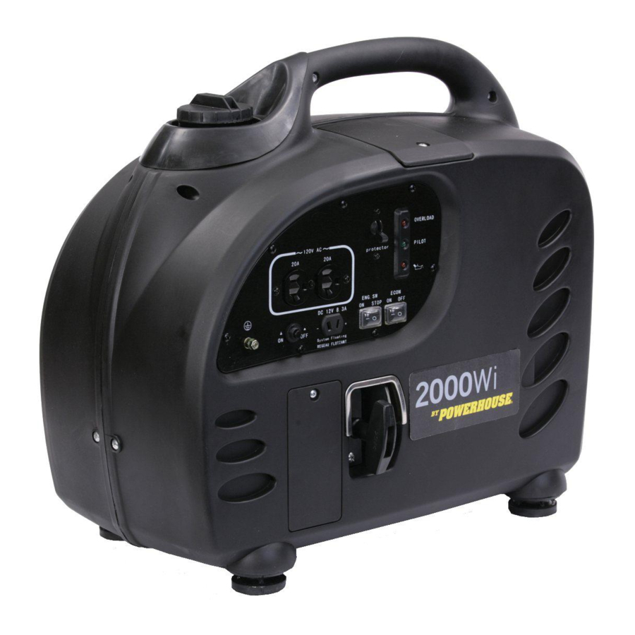
- Page 1 POWERHOUSE ® POWERHOUSE POWER PRODUCTS 2000Wi SHOP MANUAL Coast Distribution November, 2010 2000Wi SM 04-11-2012...
-
Page 2: Preface
Preface This manual covers the construction, function and servicing procedure of the POWERHOUSE® 2000Wi certificated by CARB. generator, Careful observance of these instructions will result in better, safe service work. All information, illustrations, directions and specifications included in this publication are based on the latest product information available at the time of approval for printing. -
Page 3: Table Of Contents
CONTENTS ..............................3 1. SPECIFICATIONS ............................ 5 1.1 SPECIFICATIONS ..........................5 1.2 CHARACTERISTICS .......................... 6 1.3 Wiring diagram, 2000Wi ........................7 2 Service Information ........................... 8 2.1 The importance of proper servicing ....................8 2.2 Important safety precautions ......................8 2.3 Service rules ............................ - Page 4 12. Valve cover/ Rocker arm ........................52 12.1 Disassembly/ Reassembly ......................52 12.2 Rocker Arm Inspection ........................53 12.3 Cam and cylinder head removal / Reassembly ................54 12.4 Inspection, valves and valve springs ....................57 12.5 Piston/Connection rod ........................58 2000Wi SM 04-11-2012...
-
Page 5: Specifications
Semi-dry type Governor Electronic control type Lubrication system Pump Lube oil SAE 15W-40 (SF/SG grade or greater) Oil capacity 15.6 fl oz (0.460 L) Starting system Recoil starter Stopping system Primary circuit ground Fuel used Automotive unleaded gasoline 2000Wi SM 04-11-2012... -
Page 6: Characteristics
AC circuit protector DC circuit protector Fuel tank capacity 1.4 gal (5.3L) Continuous running time at Rated load 3.0 - 7.5 hours ~ 1/4 load Noise level (Zero load to full load) 56 - 63 dB (A)/7m 2000Wi SM 04-11-2012... -
Page 7: Wiring Diagram, 2000Wi
1.3 Wiring diagram, 2000Wi 2000Wi SM 04-11-2012... -
Page 8: Service Information
To reduce the possibility of a fire or explosion, be sure when working around gasoline, use only a nonflammable solvent, not gasoline, to clean parts. Keep all cigarettes, sparks, and flames away from all fuel-related parts. 2000Wi SM 04-11-2012... -
Page 9: Service Rules
2.3 Service rules 1. Use genuine POWERHOUSE® or POWERHOUSE®-recommended parts and lubricants or their equivalents. Parts that do not meet POWERHOUSE® design specifications may damage the engine. 2. Always install new gaskets, O-rings, etc. when reassembling. 3. When tightening bolts or nuts, begin with larger-diameter or inner bolts first and tighten to the specified torque diagonally, unless a particular sequence is specified. -
Page 10: Serial Number Location
(0.0008”~0.0024”) (0.0059”) 2nd ring 0.15-0.25mm 1.0mm Ring end clearance (0.0059”~0.0098”) (0.039”) 2.0-2.3mm 1.8mm Width (0.0787”~0.0905”) (0.0590”) 1.85-1.96mm 1.75mm Height (0.0728”~0.0771”) (0.0688”) 0.03-0.18mm 0.24mm Oil ring Ring side clearance (0.001”~0.007”) (0.009”) 0.20-0.50mm 1.0mm Ring end clearance (0.0078”~0.0196”) (0.039”) 2000Wi SM 04-11-2012... -
Page 11: Motor
Primary side 0.045-0.070Ω Ignition coil Resistance 5-8k Ω — Second side 2.6 Motor Standard(Ω) Part Wire color Item 120V Ω DC winding Resistance blue-blue 0.045~0.070 Ω Sub winding Resistance white-white 0.100~0.160 Ω Main winding Resistance black-black-black 0.250~0.350 2000Wi SM 04-11-2012... -
Page 12: Torque Values
Crankcase cover M12*1.25 51.8-59.2 70-80 Flywheel nut M5 Bolt, nut 3.7~5.2 Standard torque M6 Blot, nut 6~7.4 8-10 M8 Bolt, nut 13.3~16.2 18-22 Note: Use standard torque values for fasteners that are not listed in this table. 2000Wi SM 04-11-2012... -
Page 13: Trouble Shooting
Inspect / disassemble and clean Economy switch Inspect Engine speed does not Throttle control motor (step motor) Inspect wiring / inspect motor stabilize, too faulty high or too low Inverter unit faulty Inspect / replace Valve clearance misadjusted Readjust 2000Wi SM 04-11-2012... -
Page 14: Hard Starting
3. Check the valve cone and seat times. 4. Check for worn piston, piston ring or cylinder. Normal compression Install the spark plug securely. Restart the engine according to the starting procedure. 2000Wi SM 04-11-2012... -
Page 15: Cylinder Compression Check
2. Install a compression gauge in the spark plug hole. 3. Push the engine switch in the OFF position. 4. Pull the starter rope quickly and measure the cylinder compression. Cylinder compression 65 psi (0.45Mpa) 800rpm Pressure Gauge 2000Wi SM 04-11-2012... -
Page 16: Ignition System
Set the engine switch to the “ON” position. Attach the negative (—) electrode (i.e. threaded part) of the spark plug to your ground wire and pull the recoil starter rope to check the spark plug. Ground Wire Spark Plug Spark Plug Wire 2000Wi SM 04-11-2012... - Page 17 Normal Abnormal Check the ignition coil resistance Replace the ignition coil and high pressure cable, high pressure insulation cap. Normal Abnormal Check ignition coil air gap Readjust air gap Normal Inspect or replace wire harness. 2000Wi SM 04-11-2012...
-
Page 18: Engine Oil Level Is Low, But Engine Does Not Stop
Abnormal Readjust the coil clearance Check ignition coil Normal 1. Check the valve clearance 2. Check the carbon deposit Abnormal Measure the cylinder compression in combustion chamber 3. Check the piston, piston ring and cylinder for damage 2000Wi SM 04-11-2012... -
Page 19: Engine Speed Can't Increase Or Unstable (Choke Is At The Correct Position)
Check the throttle control motor Replace the throttle control motor Normal Abnormal Check the Economy switch Replace the Economy switch Normal Abnormal Check Economy switch connection wire Repair or replace the wire harness Normal Replace the inverter unit 2000Wi SM 04-11-2012... -
Page 20: Engine Speed Doesn't Increase With Economy System "On" And A Load Connected
1. Check and repair stator wire black terminals and white terminal. Abnormal harness or replace stator 2. Rotor inner magnetism Black-Black-Black: >30V decreases, replace the rotor White-White: >1V Normal Measure stator output with unit running Abnormal Replace stator 2000Wi SM 04-11-2012... -
Page 21: Measuring Stator Output Voltage While Running
If the wire harness is the problem, find and repair the damage. 3. If the alternator is the problem, the stator will need to be replaced. If all three tests are OK, the problem is probably the inverter. 2000Wi SM 04-11-2012... -
Page 22: No Dc Output At Receptacle
Unplug the DC charge windings from Abnormal the voltage regulator and measure Check the wire harness, or the resistance. replace the stator Resistance: 0.3 Ω +/- 10% Normal Replace the voltage regulator DC Battery Charge To the Windings Voltage from Stator Regulator 2000Wi SM 04-11-2012... -
Page 23: Voltage Regulator
3.14 Voltage regulator Voltage Regulator Mounting Post From Stator Control Panel Voltage Regulator Chassis Ground Stator harness Connection 2000Wi SM 04-11-2012... -
Page 24: Maintenance Schedule
(1) For commercial use, operation hours are determined by proper maintenance. (2) Service more frequently when operating in dusty areas, every 10 hrs or every day. (3) Service by POWERHOUSE® authorized agency, unless correct tools or professional specialist is available. Do service according to the manual. -
Page 25: Checking The Oil Level
5. Refill with the recommended oil, and check the oil level. 6. Reinstall the maintenance cover and tighten the screws securely. Engine oil capacity: 15.6 oz (460 ml) Drain Pipe Upper Level Upper Level Lower Level Oil Fill Hole Dip Stick 2000Wi SM 04-11-2012... -
Page 26: Checking For The Low Oil Sensor
Ignition Coil Connector Storage Cover Low Oil sensor Connector Check Continuity between Black and Yellow/Green White and Black wires wires to oil sensor leads indicator module O.L. Jumper 2000Wi SM 04-11-2012... -
Page 27: Air Filter
If the engine is operated in dusty areas, clean the air cleaner more often than specified in the Maintenance Schedule. Never run the engine without an element or if the filter is damaged, because it will cause serious damage to the engine. 2000Wi SM 04-11-2012... -
Page 28: Spark Plug
5. Adjust by bending the side electrode if necessary. 0.6~0.7mm (0.024”~0.028”) Spark plug clearance Standard spark plug A7RTC 0.6-0.7 6. Install the plug finger tight to seat the washer, and then tighten with a plug wrench. Torque valve is 9.6~11 lbs-ft (13~15 Nm) 2000Wi SM 04-11-2012... -
Page 29: Valve Clearance
10. Turn the rotor to set the piston at top dead center of the compression stroke. The timing mark of the camshaft should be vertical to the cylinder head seal, check whether the inlet and exhaust valve are closed. Timing Mark 2000Wi SM 04-11-2012... - Page 30 After tightening the lock nut, check the valve clearance again. 12. Clean the cylinder block and cylinder head cover. Adjustment Screw Lock Nut Feeler Gauge 13. Replace the rubber seal. 14. Install the removed parts in the reverse order of removal. Rubber Seal 2000Wi SM 04-11-2012...
-
Page 31: Fuel Tank
6. Install the removed parts in the reverse order of removal. 7. Fill the fuel tank with gasoline and check the fuel hoses for gasoline leaks. 4.9 Evaporation Control Fuel Tank Vent To Air Filter Air Filter Assembly Fuel Tank Carbon Canister 2000Wi SM 04-11-2012... -
Page 32: Fuel Pump, Primer Bulb
Fuel hose from tank to Gas line from Fuel valve Pump Primmer Primmer Hose Fuel Pump Primmer Bulb Fuel valve Hose Connection Gas Tank Intake Manifold Hose Hose Connection Connection Fuel Hose Connection to Fuel Pump Carburetor 2000Wi SM 04-11-2012... -
Page 33: Muffler System
2. Remove the two M4 screws holding the spark arrester to the muffler. 3. Use a stiff wire brush to remove carbon deposits from the spark arrester screen. 4. Inspect the screen for holes, and replace it if necessary. M4 Screws Muffler Grill Spark Arrestor M6 Screws 2000Wi SM 04-11-2012... -
Page 34: Muffler
2. Remove muffler grill. 3. Remove the front and rear covers. 4. Remove fuel tank. 5. Remove the carburetor assembly. 6. Remove the carbon canister. 7. Remove front and back engine covers. Exhaust Manifold Muffler gasket Muffler Spark Arrestor 2000Wi SM 04-11-2012... -
Page 35: Exhaust Tube, Secondary Air Valve
2. Remove the control panel mounting screws. Note, it is not necessary to unplug the control panel, just push it through the opening when removing the side cover. 3. Remove two bottom foot pads and front cover. Secondary Air Valve 2000Wi SM 04-11-2012... -
Page 36: Carburetor
5. Remove the carburetor, choke and air filter as an assembly being very careful not to pull on the step motor wires. Intake manifold Carburetor Gaskets Air Box Cover Course Filter Fine Filter Filter Housing Filter cartridge 2000Wi SM 04-11-2012... - Page 37 Carbon Canister Carburetor 2000Wi SM 04-11-2012...
-
Page 38: Disassembly/Installation Of Step Motor
Step motor 步进电机座 Step motor base 拔叉弹簧 Fork spring 拔叉 Disassembly: 拆卸: Fork Carefully remove 拆卸时用手捏牢, the spring and fork 以防弹簧丢失。 拔叉 Fork 油门杆 from the throttle Throttle level lever. 拔叉弹簧 Fork spring 怠速调整限位帽 Idle adjusting cap 2000Wi SM 04-11-2012... -
Page 39: Disassembly/Installation Of Carburetor
组装: 安装后应当用手指触 Float 动,对其动作确认。 Fuel cup 油杯 油杯锁紧螺丝密封圈 Seal ring Drain screw 油杯放油螺栓 油杯螺栓 Installation: check the Fuel cup bolt 组装: 组装: fuel leakage before Installation: check the 安装后确认没有燃油 安装后确认没有燃油 installation fuel leakage before 漏出。 漏出。 installation 2000Wi SM 04-11-2012... -
Page 40: Stepping Motor
Make sure to check the step motor connection on the inverter for any debris, damaged or bent pins Measure the resistance of the step motor lead-out wire. Replace the step motor if the resistance exceeds the ranges shown below. 1-blue ~ 2-white:50~55Ω Standard resistance 3-red ~ 4-black:50~55Ω 2000Wi SM 04-11-2012... -
Page 41: Control Panel
7. Control panel 7.1 Disassembly/Installation Remove seven M4 panel screws. 120V-20A Circuit Breaker Indicator Module Module 120V-20A Cover Duplex DC Circuit Breaker DC Charge Receptacle Economy / Engine Switches 2000Wi SM 04-11-2012... - Page 42 2000Wi SM 04-11-2012...
-
Page 43: Outer Generator Housing
8. Outer generator housing 8.1 Disassembly and installation of housing case Control Panel Exhaust Grill Primmer Spark Plug Bulb Access Fuel Pump Front Cover Inverter Fuel Valve Rear Cover Fuel Lever Maintenance Cover 2000Wi SM 04-11-2012... -
Page 44: Recoil Starter / Ignition Coil
6. Remove (3) M6 flange bolts and the recoil starter. 7. Reassemble in reverse order. Gas Tank Inverter Storage Tray Recoil Assembly Bolts Remove inverter and storage tray mounting screws and bolts from the bottom of pan. 2000Wi SM 04-11-2012... -
Page 45: Ignition Coil
6. If there is no resistance remove the spark plug cap and check the lead itself. 7. Replace the spark plug cap or coil if there is no resistance or the value is outside of the values shown. 0.045-0.070 Ω Primary resistance 5-8 k Ω Secondary resistance 2000Wi SM 04-11-2012... -
Page 46: Ignition Coil / Disassembly
(Both sides need to be adjusted equally) and retighten the bolts. 3. Rotate the rotor to make sure there is no interference with the flyweights. Ignition coil gap 0.5~0.75mm Ignition Coil Permanent magnet Rotor 2000Wi SM 04-11-2012... -
Page 47: Rotor/Stator Disassembly / Reassembly
Inverter. Fan cover Starter cup and fan M12 flange nut Ignition coil Rotor M5 Stator bolts Stator Ignition Coil Stator Assembly Rotor Assembly Flange Bolts Flange Nut Starter cup 2000Wi SM 04-11-2012... -
Page 48: Stator Inspection
Measure the resistance between the two sub winding terminals. White-White Resistance Ω 0.100~0.160 (4) Main winding Measure the resistance between each of the main winding terminals. Black-Black-Black Resistance Ω 0.250~0.350 Main Windings, (Black) Windings, (White) DC Battery Charge Windings, (Blue) 2000Wi SM 04-11-2012... -
Page 49: Exploded Engine View
11. Exploded engine view 2000Wi SM 04-11-2012... - Page 50 "O" style sealing ring 09070129-31 69706 Tie bar bolt 03050313 69715 Rear oil seal 040907 60042 Timing chain guide 09070111 69701 Timing chain 09070112 69701 Timing chain guide 09070109 69705 Retainer ring 09070139 69708 Located pin for piston 09070102 2000Wi SM 04-11-2012...
- Page 51 Lock catch for valve 09070125 69682 M6 x 100 bolt 03050226 Camshaft 09070128 69669 Rocker subassembly 09070133 69644 M8 nut 03060115 69709 Valve cover gasket 09070110 69667 53,54,58,59 Valve cover/PCV 76120 69666 Assy. M6 x 25 bolt 03050241 69349 2000Wi SM 04-11-2012...
-
Page 52: Valve Cover/ Rocker Arm
2. The timing mark of camshaft should be vertical to the cylinder head seal, check whether the inlet and exhaust valve are closed. 3. Remove 4- rocker arm nuts and washers and carefully remove the rocker arm assembly Timing Mark Alignment Sleeves 2000Wi SM 04-11-2012... -
Page 53: Rocker Arm Inspection
12.2 Rocker Arm Inspection ● Rocker arm outer diameter Standard Service limit 9.96-9.97mm 9.953mm (0.392-0.393”) (0.391”) ● Rocker arm inner diameter of inlet/exhaust valve Standard Service limit 10.000-10.015mm 10.040mm (0.3936-0.3942”) (0.3952”) 2000Wi SM 04-11-2012... -
Page 54: Cam And Cylinder Head Removal / Reassembly
5. Lift and remove the cam assembly from the head. 6. Carefully inspect the cam lobes, bearings and decompression operation. ● Cam height Standard Service limit 29.026-29.086mm 29.15mm (1.143-1.145”) (1.104”) Timing Chain Tensioner Cam Bearings Decompression Intake Exhaust Fly Weight Decompression Decompression “ON” “OFF” 2000Wi SM 04-11-2012... - Page 55 (Upright) position. Install the chain onto the cam gear making sure that the timing mark is straight up before installing the rocker arm assembly. Timing Timing Mark Mark Crankshaft Keyway 2000Wi SM 04-11-2012...
- Page 56 13. Constant clockwise tension must be applied to the center screw until the tensioner is flush with the gasket before it is released. Rotate tension Screw Clockwise to Retract plunger Adjustment Screw Cover and ‘O’-Ring Normal Position The Plunger must be kept in the retracted position while reinstalling. 2000Wi SM 04-11-2012...
-
Page 57: Inspection, Valves And Valve Springs
1.0mm (0.039”) 2.0mm (0.079”) ● Valve stem outer diameter Standard Service limit 4.92mm (0.1937”) 4.975-4.99mm (0.1958-0.1964”) Intake valve 4.90mm (0.193”) 4.955-4.970mm (0.1950-0.1951”) Exhaust valve ● Valve guide inner diameter Standard Service limit 5.060mm (0.199”) 5.000-5.030mm (0.197-0.198”) Inlet/Exhaust valve 2000Wi SM 04-11-2012... -
Page 58: Piston/Connection Rod
口处。 the groove in the piston pin hole. 连杆 组装: Connection rod Installation: 将大端部较长的一侧朝向活塞的 The larger side of the 。 “ ”指向的右侧装入活塞 卡环 connection rod must be Clip ring aligned with the △ label on the piston. 2000Wi SM 04-11-2012... - Page 59 52.505mm (2.0671”) ● Piston skirt outer diameter Standard Service limit 52.360-52.380mm (2.061-2.062”) 52.25mm (2.057”) 10mm ● Side clearance of piston ring Standard Service limit 0.15mm (0.0059”) 0.02-0.06mm (0.0008-0.0024”) and 2 Ring 0.24mm (0.009”) 0.03-0.18mm (0.001-0.007”) Oil Ring 2000Wi SM 04-11-2012...
- Page 60 Locate the piston ring into cylinder with piston top, and measure the piston end clearance. Standard Service limit 1.0mm (0.039”) 0.15-0.25mm (0.0059-0.0098”) and 2 Ring 1.0mm (0.039”) 0.20-0.50mm (0.0078-0.0196”) Oil Rings ● Piston ring height Standard Service limit 0.87mm (0.0342”) 0.97-0.99mm (0.0381-0.0389”) and 2 Ring 1.75mm (0.0688”) 1.85-1.96mm (0.0728-0.0771”) Oil Rings 2000Wi SM 04-11-2012...
- Page 61 ● Piston pin outer diameter Standard Service limit 14.95mm (0.5925”) 14.994-15.008mm (0.5903-0.5905”) ● Piston pin hole inner diameter Standard Service limit 15.05mm (0.5925”) 15.002-15.008mm (0.5907-0.5908”) ● Connection rod small end inner diameter Standard Service limit 15.08mm (0.594”) 15.006-15.017mm (0.590-0.5991”) 2000Wi SM 04-11-2012...
Need help?
Do you have a question about the 2000Wi and is the answer not in the manual?
Questions and answers