Powerhouse 2000Wi Digital Inverter Generator Owner's Manual
Digital inverter generator
Hide thumbs
Also See for 2000Wi Digital Inverter Generator:
- Owner's manual (40 pages) ,
- Quick start manual (5 pages) ,
- Shop manual (61 pages)

Related Manuals for Powerhouse 2000Wi Digital Inverter Generator


Summary of Contents for Powerhouse 2000Wi Digital Inverter Generator
- Page 1 2000Wi Digital Inverter Generator By POWERHOUSE® OWNER’S MANUAL PLEASE READ THIS MANUAL CAREFULLY BEFORE USING 2000Wi OM...
-
Page 2: Quick Start Guide
Quick Start Guide Use outdoors only. Generators produce carbon monoxide — a poisonous, colorless, odorless gas that can cause death or serious injury. Always operate on a level surface Keep away from rain, snow or other wet conditions ... - Page 3 PREFACE Thank you for purchasing a POWERHOUSE generator. This manual covers operation and maintenance of POWERHOUSE generator model 2000Wi. All information in this publication is based on the latest product information available at the time of printing. We reserve the right to make changes at any time without notice and without incurring any obligation.
-
Page 4: Table Of Contents
7.3 No output at the DC receptacle: .................... 33 8. SPECIFICATIONS ........................34 9. WARRANTY AND CONSUMER INFORMATION ............... 35 POWERHOUSE® GENERATOR WARRANTY ................35 CALIFORNIA EMISSIONS CONTROL WARRANTY STATEMENT ........... 36 EMISSION CONTROL SYSTEM WARRANTY ................37 10. APENDIX B - EMISSION CONTROL SYSTEM ................ 37 11. -
Page 5: Safety Instructions
1. SAFETY INSTRUCTIONS ■ This generator is designed to give safe and dependable service if operated according to instructions. Read and understand the Owner's Manual before operating the generator. Failure to do so could result in personal injury or equipment damage. ■... - Page 6 ■ This generator is not intended, nor designed, for use as a standby power supply and should never be used as such. Severe property damage and/or severe personal injury or death may result. Never connect this generator to an automatic transfer switch (ATS). Severe damage to the generator will occur. ■...
-
Page 7: Component Identification
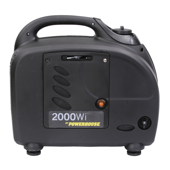
2. COMPONENT IDENTIFICATION Spark Plug Access Cover Gas Cap Control Panel Starter Grip Choke Lever Maintenance Panel Exhaust Grill Fuel Valve Primer Bulb 2000Wi OM... -
Page 8: Control Panel 2000Wi
2.1 Control panel 2000Wi 120 V - 20A Overload Light 120 V - 20A Duplex Circuit Breaker (Red) Receptacle Run Light (Red) Ground Terminal Low Oil Alarm Light (Red) Economy Switch Battery Charge Engine Switch Battery Charge Circuit Breaker Receptacle 2000Wi OM... -
Page 9: Serial Number And Bar Code Identification And Location
Date of Purchase ________________________________ Name of Selling Dealership ________________________________ Please go to www.powerhouse-products.com/register and register your unit today. Online registration will be accepted as proof of purchase. Online registration will make sure you are protected in the event you have lost your receipt, and will significantly speed the process in the event warranty service is necessary. -
Page 10: Pre-Operation Check
3. PRE-OPERATION CHECK ■ Be sure to check the generator on a level surface with the engine stopped. 3.1 Check the engine oil level. Do not use non-detergent oil or 2-stroke engine oil. It will void the warranty and will shorten the engine's service life. ... -
Page 11: Check The Fuel Level
3.2 Check the fuel level. Use automotive unleaded regular gasoline only. 1. If the fuel level is low, refill to the top of the fuel strainer. 2. Never use an oil/gasoline mixture or dirty gasoline. 3. Avoid getting dirt, dust or water in the fuel tank. 4. -
Page 12: Check The Air Cleaner
3.3 Check the air cleaner Loosen the maintenance cover screws and remove the maintenance cover. Remove three air filter retaining screws. Remove the cover and check the element. Clean or replace the element if necessary. Replace the air cleaner element, and cover. Tighten the screws securely. Replace the maintenance cover and tighten the screws securely. -
Page 13: Operating Instructions
4. OPERATING INSTRUCTIONS 4.1 Starting the engine Before starting the engine, disconnect any load from the AC receptacles. 1. Turn the fuel valve lever to the ―ON‖ position. 2. If the fuel tank was empty it may be necessary to pump the primer bulb 15 to 20 times to get fuel to the carburetor. -
Page 14: High Altitude Operation
4.2 High altitude operation At higher altitudes, the standard carburetor air-fuel mixture will be excessively rich. Performance will decrease, and fuel consumption will increase. High altitude performance can be improved by installing a smaller diameter main fuel jet in the carburetor. If you always operate the generator at altitudes higher than 5000 feet (1500 m) above sea level, have your authorized dealer install a high altitude main jet. -
Page 15: Generator Use
4.4 Generator use Be sure to ground the generator when loads are connected. ■ To prevent electrical shock from faulty appliances, the generator should be grounded. Connect a length of heavy cable between the generator's ground terminal and an external ground source. ■... - Page 16 ■ The total wattage of all appliances connected must be considered. ■ Do not exceed the current limit specified for any one receptacle. ■ Do not connect the generator to a household circuit. This could cause damage to the generator or to electrical appliances in the house. ■...
-
Page 17: Ac Application
4.5 AC application 1. Start the engine and make sure only the output run indicator light (Green) comes on. 2. Confirm that the appliance to be used is switched off before plugging into the control panel. 120 V - 20A Duplex Receptacle Run Light (Green) -
Page 18: Output And Overload Lights
4.6 Output and Overload Lights 1. The output indicator light (Green) will remain illuminated during normal operating conditions. 2. If the generator is overloaded (in excess of 2.0 kW), or if there is a short in the connected appliance, the output indicator light (Green) will go out, the overload indicator light (Red) will turn on and current to the connected appliance will be shut off. -
Page 19: Dc Application
4.7 DC application The DC receptacle may be used for charging 12 volt lead acid batteries only. Other types of batteries may burst causing personal injury or damage. To prevent the possibility of creating a spark near the battery, connect the charging cable first to the battery then to the generator. -
Page 20: Low Oil Alarm System
■ Batteries gives off explosive gases; keep spark, flames and cigarettes away. Provide adequate ventilation when charging. ■ Batteries contain sulfuric acid (electrolyte). Contact with skin or eyes may cause severe burns. Wear protective clothing and a face shield. -If electrolyte gets on your skin, flush with water. -If electrolyte gets in your eyes, flush with water for at least 15 minutes and call a physician. -
Page 21: Economy Switch
4.9 Economy switch Economy switch ―ON‖: This position is recommended to minimize fuel consumption and noise while in operation. Engine speed is kept at idle automatically when the electrical load is disconnected and returns to the proper speed to match the power of the electrical load when the load is reconnected. ■... -
Page 22: Maintenance
Carbon monoxide is a poisonous gas. The emission of fuel vapors is a source of pollution as well. The POWERHOUSE generator engine utilizes a precise air-fuel ratio and emission control system to reduce the emissions of carbon monoxide, NO , hydrocarbons, and evaporative fuel emissions. - Page 23 You can trust that replacement parts supplied by POWERHOUSE have been manufactured to the same production standard as the original parts. The use of replacement parts or accessories which are not designed by POWERHOUSE may affect the engine emission performance.
-
Page 24: Maintenance Schedule
5.2 Maintenance Schedule Regular Service period (1). Perform at every indicated month or operating hour interval, whichever occurs first. Maintenance Item Month Every 3 Months Every 6 Months 1x per Year Procedure Each Use 4 to 6 Hours 50 Hours 100 Hours 300 Hours Check... -
Page 25: Changing Oil
5.3 Changing oil Drain the oil while the engine is still warm to assure rapid and complete draining. ■ Make sure to turn the engine switch ―OFF‖ before draining the oil. 1. Loosen the cover screws and remove the side maintenance cover. 2. -
Page 26: Air Cleaner Service
5.4 Air cleaner service A dirty air cleaner will restrict air flow to the carburetor. To prevent carburetor malfunction, service the air cleaner regularly. Service more frequently when operating the generator in extremely dirty areas. ■ Do not use gasoline or low flash point solvents for cleaning. They are flammable and explosive under certain conditions. -
Page 27: Spark Plug Maintenance
5.5 Spark plug maintenance RECOMMENTED SPARK PLUG: A7RTC To ensure proper engine operation, the spark plug must be properly gapped and free of deposits. 1. Loosen the cover screw and remove the spark plug maintenance cover. Screw Spark Plug Access Cover 2. - Page 28 5. Visually inspect the spark plug. Discard it if the insulator is cracked or chipped. Clean the spark plug with a wire brush if it is to be reused. 6. Measure the plug gap with a feeler gauge. 7. The gap should be 0.024-0.028in (0.6-0.7mm). Correct as necessary by carefully bending the side electrode.
-
Page 29: Spark Arrestor Maintenance
5.6 Spark arrestor maintenance ■ If the generator has been running, the muffler will be very hot. Allow it to cool before proceeding. ■ The spark arrestor must be serviced every 100 hours to maintain its efficiency. 1. Remove the six M6 screws and remove the muffler grill. 2. -
Page 30: Transporting And Storage
6. TRANSPORTING and STORAGE 6.1 Transporting the generator When transporting the generator, it should always be secured upright in its normal operating position with the fuel valve and engine switch turned ―OFF‖. When transporting the generator: ■ Do not overfill the tank. ■... -
Page 31: Exercising The Generator
6.3 Storing the generator for an extended period 1. Be sure the storage area is free of excessive humidity and dust. 2. Regardless of whether you plan to store your generator with or without fuel, add an appropriate amount (per the instructions on the bottle) of fuel stabilizer and run the generator for 5 minutes. This will assure that any fuel trapped in the system will have the stabilizer in it. -
Page 32: Troubleshooting
Is there a spark from the Replace the an authorized spark plug? sparkplug. spark Powerhouse dealer WARNING To check spark: 1. Remove the spark plug cap and clean any ■ Be sure there is no spilled fuel dirt from around the spark plug. -
Page 33: Appliance Does Not Operate
■ Take the electrical appliance or equipment to an electrical shop for repair. 7.3 No output at the DC receptacle: Is the DC circuit breaker tripped? Reset the circuit breaker. Take the generator to an authorized Powerhouse service center. 2000Wi OM... -
Page 34: Specifications
8. SPECIFICATIONS Generator Model 2000Wi Rated frequency (Hz) Rated voltage (V) Rated current (A) 15.8 Max current (A) 16.7 Rated output (W) 1900 Max output (W) 2000 DC Output 12 V, 8.3 A Phase Single Engine Model XG-152F Type 4 stroke, vertical shaft, air-cooled, OHC, gasoline engine Displacement 125 cc Compression ratio... -
Page 35: Warranty And Consumer Information
Proof of purchase and the serial number is required. Coverage Pre-approved parts and labor costs will be covered by POWERHOUSE for any failure that is proven to be a failure in material or workmanship under normal use during the applicable warranty time period. This coverage is limited to parts, labor and ground shipping of repair parts. -
Page 36: California Emissions Control Warranty Statement
CALIFORNIA EMISSIONS CONTROL WARRANTY STATEMENT Your Warranty Rights and Obligations The California Air Resources Board and The Coast Distribution System, Inc. (POWERHOUSE) are pleased to explain the emissions control system warranty on your 2008 and later small off-road engine (SORE). In California, new SOREs must be designed, built, and equipped to meet the State's stringent anti-smog standards. -
Page 37: Emission Control System Warranty
3. A catalyst is built into the muffler to further treat the engine exhaust. 4. A secondary air injection valve adds combustion air to ignite unburned fuel in the exhaust. Contact your authorized POWERHOUSE service center to obtain the correct replacement parts and service on this system. -
Page 38: Apendix C - Safety And Charging Instructions
11. APENDIX C - SAFETY AND CHARGING INSTRUCTIONS (a) SAVE THESE INSTRUCTIONS. THIS MANUAL CONTAINS IMPORTANT SAFETY AND OPERATING INSTRUCTIONS. (b) WORKING IN THE VICINITY OF A LEAD-ACID BATTERY IS DANGEROUS. BATTERIES GENERATE EXPLOSIVE GASES DURING NORMAL BATTERY OPERATION. FOR THIS REASON IT IS OF THE UTMOST IMPORTANCE THAT EACH TIME BEFORE USING YOUR CHARGER, YOU READ AND FOLLOW THE INSTRUCTIONS PROVIDED EXACTLY. - Page 39 CONNECT THE NEGATIVE (BLACK) CLIP TO VEHICLE CHASSIS OR ENGINE BLOCK AWAY FROM BATTERY. DO NOT CONNECT CLIP TO CARBURETOR, FUEL LINES, OR SHEET-METAL BODY PARTS. CONNECT TO A HEAVY GAUGE METAL PART OF THE FRAME OR ENGINE BLOCK; vi. FOR A POSITIVE-GROUNDED VEHICLE, CONNECT THE NEGATIVE (BLACK) CLIP FROM BATTERY CHARGER TO NEGATIVE (NEG, N, –) UNGROUNDED POST OF BATTERY.
- Page 40 350 Woodview Ave., Suite 100 Morgan Hill, CA 95037 www.powerhouse–products.com 2000Wi OM (Revision – 2011-04-12)
Need help?
Do you have a question about the 2000Wi Digital Inverter Generator and is the answer not in the manual?
Questions and answers