
Related Manuals for Powerhouse PH2200i


Summary of Contents for Powerhouse PH2200i
- Page 1 POWERHOUSE ® PH2200i Digital Inverter Generator Owner’s Manual PLEASE READ THIS MANUAL CAREFULLY BEFORE OPERATING THE GENERATOR...
-
Page 2: Table Of Contents
SAFETY INSTRUCTIONS ................................. 5 COMPONENT IDENTIFICATION ..............................6 2.1. PH2200i Generator ....................................6 2.2. PH2200i Control Panel ..................................7 2.3. Generator Identifi cation Numbers ................................ 8 SETUP & PRE-OPERATION CHECKS ............................9 3.1. Checking and Adding Engine Oil ................................9 3.2. -
Page 3: Preface
Thank you for purchasing a POWERHOUSE generator. ® This manual covers the operation and maintenance of the POWERHOUSE inverter generator model PH2200i. ® This manual should be considered a permanent part of the generator and should remain with it if it is resold. -
Page 4: Quick Start
▲ Make sure that appliances are switched off , in good working condition, and that the combined electrical rating of all connected appliances does not exceed that of the generator (2200W max). For shutdown, see Stopping the Generator. NOTE PH2200i Owner’s Manual v.1 (English) -
Page 5: Safety Instructions
▲ Generators are a potential source of electrical shocks when misused; do not operate with wet hands. ▲ Do not operate the generator in rain or snow and do not let it get wet. ▲ Do not modify the enclosure of this generator. PH2200i Owner’s Manual v.1 (English) -
Page 6: Component Identification
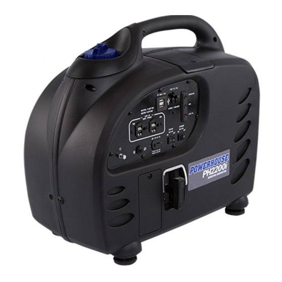
2.1. PH2200i GENERATOR FRONT OF GENERATOR, RIGHT SIDE Gas Cap Spark Plug Access Door Control Panel Starter Grip BACK OF GENERATOR, LEFT SIDE Manual Choke Lever Exhaust Grille Maintenance Door Fuel Primer Bulb Fuel Valve PH2200i Owner’s Manual v.1 (English) -
Page 7: Ph2200I Control Panel
60HZ 1PHASE (green) LOW OIL Low Oil (red) ENGINE ECONOMY SWITCH SWITCH DC 12V 8.3A Ground Terminal SYSTEM FLOATING RESEAU FLOTTANT Engine Economy DC 12V 8.3A DC Circuit Switch Switch Receptacle Breaker (External Battery Charging) PH2200i Owner’s Manual v.1 (English) -
Page 8: Generator Identification Numbers
Name of Selling Dealership Warranty Registration Please go to www.powerhouse-products.com/register and register your unit today. Online registration will be accepted as proof of purchase. Online registration will make sure you are protected in the event you have lost your receipt, and will signifi cantly speed up the process in the event warranty service is necessary. -
Page 9: Setup & Pre-Operation Checks
3. Check the oil level and add oil if necessary. a. Insert the dipstick back into the oil reservoir. (To ensure an accurate reading, do not tighten or screw the dipstick into the reservoir.) Remove it, and check the oil level. PH2200i Owner’s Manual v.1 (English) - Page 10 ▲ The low oil alarm system will automatically stop the engine before the oil level falls below a safe limit. However, to avoid the inconvenience of an unexpected shutdown, it is still advisable to visually inspect the oil level regularly. PH2200i Owner’s Manual v.1 (English)
-
Page 11: Checking And Adding Fuel
▲ Fuel system damage or engine performance problems resulting from the use of gasoline that contains an improper ethanol blend, or from adding oil to the fuel, are not covered under warranty. PH2200i Owner’s Manual v.1 (English) -
Page 12: Startup & Operation
• A half-closed choke (in the 1/2 position) enables a warm engine to start easier. • An open choke (in the RUN position) enables a hot engine to start easier. 4.1.1. Basic Choke Settings for Startup and Operation Manual Choke Start START open closed (no choke) (full choke) PH2200i Owner’s Manual v.1 (English) -
Page 13: Adjusting The Choke For Environmental And Engine Temperatures
In most circumstances, no choke is needed for a warm or hot engine. Start and run the generator with the choke in the RUN position. If the engine does not start, move the choke to the 1/2 or START position and try again. PH2200i Owner’s Manual v.1 (English) -
Page 14: Starting The Generator
▲ Make sure that appliances are switched off , in good working condition, and that the combined electrical rating of all connected appliances does not exceed that of the generator (2200W max). For shutdown, see Stopping the Generator. NOTE PH2200i Owner’s Manual v.1 (English) -
Page 15: Environmental Impacts On Generator Performance
▲ Be sure to have any carburetor modifi cation reversed before operating at lower altitudes. Operation CAUTION of the generator at an altitude lower than the carburetor is jetted for may result in reduced performance, overheating, and serious engine damage caused by an excessively lean air/fuel mixture. PH2200i Owner’s Manual v.1 (English) -
Page 16: Extreme Temperatures
– NOTES In freezing temperatures, allow the generator to warm up for 3 to 5 minutes before connecting heavy loads. – For details, see Adjusting the Choke for Environmental and Engine Temperatures. PH2200i Owner’s Manual v.1 (English) -
Page 17: Using The Generator
• 14 Gauge Cords - a 14 gauge cord between 0 and 50 feet long will safely handle tool and appliance loads between 10 and 15 amps. • 12 Gauge Cords - a 12 gauge cord between 50 and 100 feet will safely handle tool and appliance loads between 10 and 15 amps. PH2200i Owner’s Manual v.1 (English) -
Page 18: Run & Overload Lights
• Appliances are turned off and in good working condition without faulty performance or electrical shorts. • The combined electrical rating of all connected appliances does not exceed the maximum power output rating (2200W) for the generator. PH2200i Owner’s Manual v.1 (English) -
Page 19: Low Oil Alarm System
5V USB 2.0A OVERLOAD NEUTRAL FLOATING NEUTRE FLOTTANT CIRCUIT BREAKER 120V AC 20A 60HZ 1PHASE LOW OIL ENGINE ECONOMY SWITCH SWITCH DC 12V 8.3A SYSTEM FLOATING RESEAU FLOTTANT 3. Turn the fuel valve to the OFF position. PH2200i Owner’s Manual v.1 (English) -
Page 20: Ac Application
The AC neutral wire is not connected to the system ground. If you check the receptacles on this generator with a receptacle tester, the ground circuit condition will appear diff erent than it would for a receptacle in your home. PH2200i Owner’s Manual v.1 (English) -
Page 21: Dc Application
When the generator is running, you can use Smart USB ports for powering small electronic devices. Both ports can be used at the same time to draw 1.0A each, or you can use only one port to draw a maximum of 2.0A. PH2200i Owner’s Manual v.1 (English) -
Page 22: Charging An External 12V Battery
4. On the control panel, connect the V-style end of the charging cable to the DC receptacle. 12V DC Circuit Breaker Charging Wires 5. When charging is complete, disconnect the charging cable from the generator, then disconnect from the battery. PH2200i Owner’s Manual v.1 (English) -
Page 23: Maintenance
(3) These items should be serviced by an authorized dealer unless the owner has the proper tools and is mechanically profi cient. Service Period for Oil Changes Normal Operating Temperature Normal –100 hr 77°F (25°C) 95 hr 86°F (30°C) 85 hr 95°F (35°C) 70 hr 104°F (40°C) PH2200i Owner’s Manual v.1 (English) -
Page 24: Changing The Engine Oil
4. Tilt the generator to drain the dirty oil into a container. Be sure to allow time for the oil to drain completely. ▲ Use caution when draining hot oil from an engine that can cause severe burns. CAUTION Oil drain pipe PH2200i Owner’s Manual v.1 (English) - Page 25 Please dispose of used motor oil in a manner that is compatible with the environment and local disposal NOTE regulations. Do not throw it in the trash or pour it on the ground. PH2200i Owner’s Manual v.1 (English)
-
Page 26: Cleaning The Air Filter Element
4. Inspect the air fi lter element. If the element is dirty, wash it in a soapy solution and let it dry thoroughly. 5. Place the air fi lter element back into the air fi lter cartridge. 6. Reinstall the air fi lter cartridge and screws. 7. Reinstall the maintenance door and screws back onto the generator. PH2200i Owner’s Manual v.1 (English) -
Page 27: Cleaning The Spark Plug
6. Clean the spark plug with a wire brush. 7. Measure the plug gap with a feeler gauge. The gap should be 0.024-0.028 in. (0.6-0.7mm). Adjust the gap as needed by carefully bending the side electrode. 0.024-0.028” (0.6-0.7mm) PH2200i Owner’s Manual v.1 (English) - Page 28 For a new spark plug, tighten by a 1/2 turn in order to adequately compress the gasket. NOTE 9. Put the spark plug cap back on the spark plug securely. 10. Reinstall the spark plug access door and screw back onto the generator. PH2200i Owner’s Manual v.1 (English)
-
Page 29: Cleaning The Spark Arrestor
4. Use a wire brush to remove any carbon deposits from the spark arrestor screens. Brush off any deposits from both the front and back screen material. Brush any buildup off both screens 5. Reinstall the spark arrestor and two screws. 6. Reinstall the exhaust grille and the six screws back onto the generator. PH2200i Owner’s Manual v.1 (English) -
Page 30: Transporting And Storing The Generator
Turn the fuel valve to the ON position and drain the remaining gasoline from the fuel tank. e. With the drain screw off , disconnect the spark plug wire and pull the starter grip 3 to 4 times to drain the gasoline from the fuel pump. PH2200i Owner’s Manual v.1 (English) -
Page 31: Exercising The Generator
(such as STA-BIL ) to help prevent fuel oxidation ® (breakdown) and the formation of gum and varnish, and to inhibit corrosion in the fuel system and carburetor. PH2200i Owner’s Manual v.1 (English) -
Page 32: Troubleshooting
3. Attach the plug side electrode to your ground wire. 4. Pull the recoil starter -- sparks should jump across the spark plug gap. Spark plug cap Ground wire Spark plug PH2200i Owner’s Manual v.1 (English) -
Page 33: Appliance Does Not Operate
8.3. NO OUTPUT AT THE DC RECEPTACLE Is the DC circuit breaker tripped to "OFF"? Reset the DC circuit breaker. Take the generator to an authorized POWERHOUSE service center. ® PH2200i Owner’s Manual v.1 (English) -
Page 34: Specifications
0.004±0.001 in. (0.10±0.02mm) Valve clearance (exhaust) 0.006±0.001 in. (0.15±0.02mm) Dimensions Overall dimensions - H x W x D in. (mm) 19.1 X 11.3 x 21.3 in. (485 x 287 x 541 mm) Dry weight 63.5 lbs. (28.8kg) PH2200i Owner’s Manual v.1 (English) -
Page 35: Warranty And Consumer Information
® the serial number are required. Coverage Pre-approved parts and labor costs will be covered by POWERHOUSE for any failure that is proven to be a failure in material ® or workmanship under normal use during the applicable warranty time period. This coverage is limited to parts, labor and ground shipping of repair parts. -
Page 36: California Emission Control Warranty Statement
) can not deny warranty solely for the lack of receipts or for your failure to ensure the performance of all scheduled maintenance. • As the SORE owner, you should however be aware that Keystone Automotive Operations, Inc. (POWERHOUSE ) may ®... -
Page 37: Emission Control System Warranty
• Secondary air injection assembly Miscellaneous • Pipes, tubes, hoses and clamps, o-rings, seals, and gaskets associated with the above systems. * Covered up to the fi rst scheduled replacement only. See the Maintenance Schedule. PH2200i Owner’s Manual v.1 (English) -
Page 38: Appendix A - Emission Control System
® production standard as the original parts. The use of replacement parts or accessories which are not designed by POWERHOUSE ® may aff ect the engine emission performance. The manufacturers of replacement parts and accessories have the responsibility to guarantee that their replacement products will not adversely aff... - Page 39 Refer to the Warranty section of this owner’s manual for more information. The air quality index label is designed to be permanently affi xed to the generator and removal should not be attempted. (Example Label) PH2200i Owner’s Manual v.1 (English)
-
Page 40: Appendix B - Vehicle Battery Charging Safety And Instructions
(p) THE GENERATOR (STATOR WINDING) IS ISOLATED FROM THE FRAME AND FROM THE AC RECEPTACLE GROUND PIN. (q) ELECTRICAL DEVICES THAT REQUIRE A GROUNDED RECEPTACLE PIN CONNECTION WILL NOT FUNCTION IF THE RECEPTACLE GROUND PIN IS NOT FUNCTIONAL. PH2200i Owner’s Manual v.1 (English) - Page 41 This page is blank. PH2200i Owner’s Manual v.1 (English)
- Page 42 7930 S.W. Burns Way, Unit C Wilsonville, OR 97070 www.powerhouse-products.com BCN # Label For This Unit This manual version applies to BCNs equal to or greater than: PH2200i Owner’s Manual (Revision 2017-10-17, v.1 © DTS Manufacturing, 2017 17121550190560001 All rights reserved.
Need help?
Do you have a question about the PH2200i and is the answer not in the manual?
Questions and answers