
Related Manuals for Grace Felix


Summary of Contents for Grace Felix
- Page 1 2 Channel Instrument Preamplifier / EQ / Blender Owner’s Manual Rev. A Grace Design, 4689 Ute Highway, Lyons, CO 80503 303.823.8100 / info@gracedesign.com www.gracedesign.com...
-
Page 2: Table Of Contents
And now you can welcome Felix to the latter category. Most of all, we made Felix so you can make great music. So read this manual and then get back to work! Regardless of where you end up playing, from here on when... -
Page 3: Safety Marking Symbols
Super rugged 1/4” connectors with heavy duty metal bushings • Universal 100-240 AC power supply with standard IEC cable – no wall wart - take Felix anywhere in the world! • Powerful, independent EQ on both channels – hi and low shelving and full parametric midrange •... -
Page 4: Top Panel Controls And Features
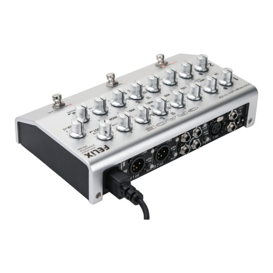
5 Top Panel Controls and Features 2.3k 3.6k 6.4k 2.3k 3.6k 6.4k 13 14 Gain controls (Ch1&2) Signal / clip LED indicator (Ch1&2) High Pass Filter (notch) / Notch filter (Ch1&2) Low frequency shelving cut and boost (Ch1&2) Parametric Midrange cut and boost (Ch1&2) Parametric Midrange frequency select (Ch1&2) Parametric Midrange Q factor (Ch1&2) High frequency shelving cut and boost (Ch1&2) -
Page 5: Back Panel Controls And Features
6 Back Panel Controls and Features PUSH Universal 100-240VAC power supply input module 10. Amp Output Ground lift switch 11. Tuner Output Ch1 DI output 12. Effects Insert Ch1 DI output source select 13. Amp Source Select switch Ch1 DI output line / mic level select 14. -
Page 6: Connecting Felix To Stuff
This is provided for folks Ch1: med - 1MΩ / hi -10MΩ / low – 10kΩ who will keep their Felix in a rack, on top of an amp, mounted Ch2: med - 1MΩ / hi -20MΩ / low – 332kΩ... -
Page 7: 100-240Vac Power Input
Felix is powered by a universal AC power supply. This means that no matter where your musical wanderings take you, you can plug Felix in to the wall and it will work. And it also means one less wall wart you’ll own in your life. All units are shipped 9 Operation features that can help make that happen. -
Page 8: Filtering And Eq
Simply put, use the high pass filter to cut unwanted bass at the input of Felix. And, as with 48V phantom power in the XLR frequencies out of a signal. Usually a HPF is used to eliminate... -
Page 9: Output Controls
High The Low control of the Felix preamplifier is fixed at 125Hz (+- The High control of the Felix preamplifier is set with a 2kHz 3dB) corner frequency / 40Hz peak, with a gain range of -12 (+/-3dB) corner frequency/ 12kHz peak, with a gain range of to +12dB. -
Page 10: Footswitch Controls
Blend – A/B DIP Switches This is the far left foot switch on Mr. Felix. If the unit is set to blend mode via DIP switch # 6, then this switch will do nothing, This is a bank of 6 DIP switches, used to activate various modes and both adjacent LEDs will be permanently illuminated. -
Page 11: Diagrams
10.1 INSERT CABLE WIRING SEND 1/4" TS PLUG To Outboard Input Jack RING RETURN 1/4" TRS PLUG SLEEVE To Felix Insert Jack 1/4" TS PLUG To Outboard Output Jack 10.2 EXTERNAL FOOTSWITCH WIRING RING MUTE BOOST SLEEVE 1/4" TRS PLUG... -
Page 12: Adjusting Internal Jumpers
IMPORTANT: Before you do anything, disconnect Felix from the AC power, and disconnect instrument and mic cables and place Felix on a flat stable surface with good lighting. DOUBLE CHECK: Did you completely disconnect the power supply? Ok then. -
Page 13: Internal Jumper Locations
10.4 INTERNAL JUMPER LOCATIONS J18 - Sets the Ch1 EQ LOW corner frequency. LO position is 125Hz, HI position is 250Hz. J17 - Sets the Ch2 EQ LOW corner frequency. LO position is 125Hz, HI position is 250Hz. J23 - Sets the secondary external footswitch function. Options are boost, toggle or disable. Primary footswitch function is fixed as MUTE / TUNE. -
Page 14: Block Diagram
10.5 BLOCK DIAGRAM... -
Page 15: Connection Diagram
10.6 CONNECTION DIAGRAM... -
Page 16: Specifications
11 Specifications GAIN RANGE (Input to DI Output) CH1 MIC 21-62dB CH1 Inst Low Gain: 3-44dB / High Gain / 21-62dB CH2 Inst -1.5-36.5dB Boost 0-9dB THD+N 1kHz, 22Hz-22kHz BW (MIC Input to DI Output) @ 20dB Gain +10dBu out <0.0045% @ 40dB Gain +10dBu out <0.0050%... -
Page 17: Cleaning And Maintenance
In no event will Grace Design be liable for lost profits or any other incidental, consequential or Exemplary damages, even if Grace Design is aware of the possibility of such damages. In no event will Grace Design’s liability exceed the purchase price of the product. -
Page 18: Manual Revisions
14 Manual Revisions Revision Page Change Date Initials Initial release 05/08/2015...
Need help?
Do you have a question about the Felix and is the answer not in the manual?
Questions and answers