
Related Manuals for Baldwin Boxall BVRD series


Summary of Contents for Baldwin Boxall BVRD series
-
Page 1: Installation Instructions
BVRD Series Microphones Installation Instructions Firmware version: BVRDMIC V1.09 Manual name: BVRD Series Microphones Issue: 5 ECR: 2785 Date of issue: Nov 2013... - Page 2 BVRD Series Microphones Installation Instructions © Nov 2013 Baldwin Boxall Communications Limited Wealden Industrial Estate Farningham Road, Jarvis Brook Crowborough East Sussex TN6 2JR Telephone: +44 (0)1892 664422 Facsimile: +44 (0)1892 663146 Email: mail@baldwinboxall.co.uk Website: http://www.baldwinboxall.co.uk This equipment has been designed and manufactured to conform to the following...
-
Page 3: Table Of Contents
Installation Instructions Amendment Record ___________________________________ v Proprietary Notice ____________________________________ v Safety Information ___________________________________ vi Comments_________________________________________ vi Introduction The BVRD Series Microphones Range ______________________2 Microphone Options & Features __________________________2 Technical Specification _________________________________3 Installation BMS8 Termination Box_________________________________5 Cable Identification____________________________________6 Colour Code for Processor Bypass switch - - - - - - - - - - - - - - - - 6... - Page 4 Common / System Faults - - - - - - - - - - - - - - - - - - - - - - - 17 BVRD Series Microphones Fault Indicators - - - - - - - - - - - - - - - 17...
-
Page 5: Amendment Record
Baldwin Boxall Communications Limited. The possession of this manual and the use of the information is, therefore, restricted only to those persons duly authorised by Baldwin Boxall Communications Limited. Do not reproduce, transcribe, store in a retrieval system or translate into any language, any part of this manual without the prior permission of Baldwin Boxall Communications Limited. -
Page 6: Safety Information
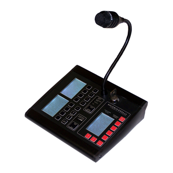
: Do not speak into the microphone until the "Speak Now" LED is illuminated. OMMENTS Comments regarding the content of this manual are welcome and should be addressed to mail@baldwinboxall.co.uk. BVRD Series Microphones issue 5... - Page 7 BVRD Series Microphones Installation Instructions 1 Introduction The BVRD Series Microphones have been designed to provide a wide variety of features suitable for any installation. Figure 1.1 — Typical BVRD8 Microphone The Microphones are configured during commissioning via an internal USB port and communicate with the main control system via an RS485 serial data link.
-
Page 8: The Bvrd Series Microphones Range
1.2 M & F ICROPHONE PTIONS EATURES All microphones in the BVRD Series include the following features as standard: • Fully monitored microphone, speech and data paths • Ergonomic design with all buttons and displays mounted behind a stylish overlay •... -
Page 9: Technical Specification
(W x H) BVRD8 188mm x 182mm BVRD16 258mm x 182mm BVRD24 328mm x 182mm BVRD32 398mm x 182mm : The RS485 Protocol is configured during the commissioning process, the default values are shown above. BVRD Series Microphones issue 5... -
Page 10: Installation
BVRD Series Microphones Installation Instructions BVRD Series Microphones issue 5... -
Page 11: Bms8 Termination Box
The BMS8 Termination Box has a standard RJ45 socket to allow use of a standard CAT5 network cable to connect to the microphone. Care must be taken to ensure this socket is not used for any other equipment since it may be damaged if connected. BVRD Series Microphones issue 5... -
Page 12: Cable Identification
ECOMMENDED ABLE YPES The BVRD Series Microphones should be terminated to 2 x 4 core Fire Rated cable (MICC/ FP200 or similar). It is strongly recommended that separate cables be used for the audio pair to eliminate potential interference from the RS485 data. -
Page 13: Firmware Configuration
Right Hand side-panel, then carefully remove the side-panel. Figure 3.1 — BVRD USB Socket for configuration : The BVRD Microphone must be powered from a 24V DC supply via the RJ45 connector before configuration is possible. BVRD Series Microphones issue 5... -
Page 14: Bvrd Usb Config Software
4. Re-connect the RJ45 lead while holding the “Speak” button, 5. Unit will show a confirmation to load Factory Default settings. Default configuration values will then be loaded into the unit. The default configuration settings are shown in Table 3.1. BVRD Series Microphones issue 5... -
Page 15: Clearing "Latched" Line Faults
LEARING ATCHED AULTS The BVRD Series Microphones can be configured to “Latch” line faults. If a Line Fault is detected by the system, the microphone can be set to keep displaying the fault even after the fault has been cleared. This is normally used as a Fault Finding Aid. -
Page 16: Temporary "Buzzer Mute
This forces a rescan to detect the correct number of zone buttons. 1. Turn the “Emergency Mode” Keyswitch 45°, and press and hold the DVA message “HOME” button. 2. Press and release the “Fault Accept” button. 3. Release the “Home” button and turn off the keyswitch. BVRD Series Microphones issue 5... -
Page 17: Operating Instructions
Volume Control Buttons Fault Accept / Lamp Test Button Priority "All Call" Button "Speak" (Press to Talk) Button Note: This is a Factory Fit Option AUX Select (BGM) Button and is for Emergency Use only. BVRD Series Microphones issue 5... -
Page 18: Viewing The Current Status Of The System
The Zone Status LCD Display (Item F in Figure 4.1) shows the names of the Messages, if they are currently being broadcast and also if any faults are present. Figure 4.3 — Typical Message LCD Display BVRD Series Microphones issue 5... -
Page 19: In "Paging" Mode (Keyswitch Not Turned)
The zone status displays will show the BVRD microphone as the source for the relevant zones. 3. Speak slowly and clearly, ensuring the “MAX” indicator does not illuminate. 4. When the announcement in finished, release the “SPEAK” Button. BVRD Series Microphones issue 5... -
Page 20: To Broadcast Bgm (Background Music) To Selected Zones
3. Press the “SPEAK” button to confirm cancellation. 4.3.5 Emergency (DVA) Messages in Paging Mode It is not possible to select Emergency (DVA) Messages in Paging Mode i.e. without the keyswitch turned 45°. This prevents accidental or unauthorised DVA Message broadcast. BVRD Series Microphones issue 5... -
Page 21: In "Emergency" Mode (Keyswitch Turned 45°)
The zone status displays will show the BVRD microphone as the source for the relevant zones. 3. Speak slowly and clearly, ensuring the “MAX” indicator does not illuminate. 4. When the announcement in finished, release the “SPEAK” Button. BVRD Series Microphones issue 5... -
Page 22: To Play A Dva Message To All Zones
1. Press the Zone Selection button (Item B in Figure 4.1) for the required zones. 2. Press the “Message Cancel” button (Item G in Figure 4.1). : It is possible to cancel different DVA Messages at the same time. BVRD Series Microphones issue 5... -
Page 23: Fault Reporting
Remedial action should be taken as soon as possible to correct faults as they impair the correct operation of the system. 4.5.2 BVRD Series Microphones Fault Indicators The BVRD Series Microphones include three fault indicators to show the following faults: • “COMMS FAULT”: The BVRD Microphone cannot communicate with the system via RS485 data. - Page 25 BVRD Series Microphones Installation Instructions BVRD Series Microphones issue 5...
- Page 26 BVRD Series Microphones Installation Instructions BVRD Series Microphones issue 5...
Need help?
Do you have a question about the BVRD series and is the answer not in the manual?
Questions and answers