Baldwin Boxall BVRDTSM Installation Instructions Manual
Touchscreen microphone
Hide thumbs
Also See for BVRDTSM:
- Installation instructions manual (32 pages) ,
- Basic user's manual (3 pages)

Related Manuals for Baldwin Boxall BVRDTSM


Summary of Contents for Baldwin Boxall BVRDTSM
- Page 1 BVRDTSM Touchscreen Microphone Installation Instructions Manual name: BVRDTSM Touchscreen Microphone Issue: 6 ECR: 4436 Date of issue: Oct 2021...
- Page 2 BVRDTSM Touchscreen Microphone Installation Instructions © Oct 2021 Baldwin Boxall Communications Limited Wealden Industrial Estate Farningham Road Crowborough East Sussex TN6 2JR Telephone: +44 (0)1892 664422 Email: hello@baldwinboxall.co.uk Website: http://www.baldwinboxall.co.uk This equipment has been designed and manufactured to conform to both CE &...
-
Page 3: Table Of Contents
Cabling and Connection details - - - - - - - - - - - - - - - - - - - - 14 BMS8/16 Termination Box _____________________________ 14 Recommended Cable Types ____________________________ 15 Operating Instructions Controls & Indicators _________________________________ 17 Operation _________________________________________ 18 BVRDTSM Touchscreen Microphone issue 6... - Page 4 Import/Export - - - - - - - - - - - - - - - - - - - - - - - - - - - - 30 Firmware - - - - - - - - - - - - - - - - - - - - - - - - - - - - - - 30 BVRDTSM Touchscreen Microphone issue 6...
-
Page 5: Amendment Record
Baldwin Boxall Communications Limited. The possession of this manual and the use of the information is, therefore, restricted only to those persons duly authorised by Baldwin Boxall Communications Limited. Do not reproduce, transcribe, store in a retrieval system or translate into any language, any part of this manual without the prior permission of Baldwin Boxall Communications Limited. -
Page 6: Safety Information
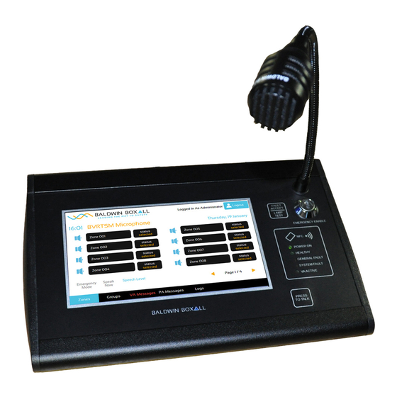
: Do not speak into the microphone until the "Speak Now" LED is illuminated. OMMENTS Comments regarding the content of this manual are welcome and should be addressed to hello@baldwinboxall.co.uk. BVRDTSM Touchscreen Microphone issue 6... - Page 7 BVRDTSM Touchscreen Microphone Installation Instructions 1 Introduction The BVRDTSM Touchscreen Microphone has been designed to provide a wide variety of features suitable for any installation. Figure 1.1 — BVRDTSM Microphone The Microphone is configured during commissioning using the in built touchscreen. Standard RJ45 Network cable connections (carrying both Audio and Serial Data) are employed, in order to make installation simple and flexible.
-
Page 8: Microphone Options & Features
1.1 M & F ICROPHONE PTIONS EATURES The BVRDTSM microphone includes the following features as standard: • Fully monitored microphone, speech and data paths • Ergonomic design with all buttons and displays mounted behind a stylish overlay • Performs as a Paging microphone (with emergency options... -
Page 9: Technical Specification
115200 Baud, 8 bit, Even Parity, 1 Stop Bit Dimensions (W x H x D) BVRDTSM 275mm x 48mm x 177mm : The RS485 Protocol is configured during the commissioning process, the default values are shown above. BVRDTSM Touchscreen Microphone issue 6... - Page 10 BVRDTSM Touchscreen Microphone Installation Instructions BVRDTSM Touchscreen Microphone issue 6...
-
Page 11: Installation
ONFIGURATION PTIONS There are four hardware configuration options accessible by removing the left and right side panels of the BVRDTSM. These options and functions are shown in the following sections: 2.1.1 Options behind RH Side Panel Figure 2.1 — BVRDTSM RH Hardware Options Table 2.1 —... -
Page 12: Options Behind Lh Side Panel
: * If park is selected "Protocol Faults (BVRD2M MB F/W 2.00 and above)" must be also be disabled in the configuration. This enables compatability with legacy systems 2.1.2 Options behind LH Side panel Figure 2.2 — BVRDTSM LH Hardware Options Table 2.2 — BVRDTSM LH Hardware Options Figure Marked as... -
Page 13: Audio Outputs
2.2 A UDIO UTPUTS The BVRDTSM is equipped with 2 Audio Outputs OP1 and OP2. OP1 is used for Live paging broadcasts. OP2 can be configured for AUX Output (broadcast of microphone stored non-emergency messages or routing of local... -
Page 14: Hardware Required
• BVRDIF7 - required to terminate the site wiring to a Voice Alarm rack (If a bypass input on a BVRD2M or BVRD2M4 is to be used by the BVRDTSM and the microphone is not configured for Bypass ensure the corresponding ZENER/ PARK jumper on the BVRDIF7 is set to ZENER) •... -
Page 15: Cabling And Connection Details
RS485-B RS485-B Audio CH1 (Paging) Audio CH1 (Paging) Audio CH1 (Paging) Audio CH1 (Paging) 4 Core 2 Audio CH2 (AUX) Audio CH2 (AUX) Audio CH2 (AUX) Audio CH2 (AUX) Shield of cable 1&2 Not Used BVRDTSM Touchscreen Microphone issue 6... -
Page 16: Configuration Option - Live Page & Hardwired Bypass
: Broadcasting of microphone stored messages or local background music source is not possible in this configuration 2.4.2 Hardware Required In order to support this BVRDTSM configuration the following additional equipment is required; • BMS8 - required to terminate the BVRDTSM microphone CAT6A lead to site wiring •... -
Page 17: Hardware Configuration
Don’t Care* Resistor +3V3 / Park Must match the hardwired bypass access level of the connected Baldwin Boxall router (3V3 = 3V3, Park = 10V) : * see section section 2.1 above for more information 2.4.4 Cabling and Connection details Please see Table below for details of Site Wiring connections;... -
Page 18: Configuration Option - Live Paging, Aux And Hardwired Bypass
• Performing an All Call utilising the Hardwired Bypass inputs of a Baldwin Boxall router. 2.5.2 Hardware Required In order to support this BVRDTSM configuration the following additional equipment is required; • BMS16 - required to terminate the BVRDTSM microphone OP1 and OP2 to site wiring •... -
Page 19: Hardware Configuration
Don’t Care* Resistor +3V3 / Park Must match the hardwired bypass access level of the connected Baldwin Boxall router (3V3 = 3V3, Park = 10V) : * see section section 2.1 above for more information BVRDTSM Touchscreen Microphone issue 6... -
Page 20: Cabling And Connection Details
Not Used Shield of cable 3 2.6 BMS8/16 T ERMINATION As shown above all BVRDTSM microphone CAT6A connections should be terminated to a BMS8 or BMS16 termination box. AU T ION The BMS8/16 Termination Boxes have a standard RJ45 socket to allow use of standard CAT6A network cables to connect to the microphone.... -
Page 21: Recommended Cable Types
ECOMMENDED ABLE YPES The BVRDTSM Touchscreen Microphone BMS8 should be terminated to Fire Rated cable (MICC/ FP200 or similar). It is strongly recommended that Audio is not routed down the same cable as RS485 data as shown in the Configuration Options above. - Page 22 BVRDTSM Touchscreen Microphone Installation Instructions BVRDTSM Touchscreen Microphone issue 6...
-
Page 23: Operating Instructions
BVRDTSM Touchscreen Microphone Installation Instructions 3 Operating Instructions 3.1 C & I ONTROLS NDICATORS Figure 3.1 — BVRDTSM Controls and Indicators Table 3.1 — BVRDTSM Controls and Indicators Function Description Zone Select Press to select / de-select zones Zone Status... -
Page 24: Operation
Used to scroll between zone pages if more than 8 zones configured Speak Now Indicator Indicates when a pre-announcement chime has finished playing Emergency Mode Indicator Indicates that the BVRDTSM is currently in Emergency Mode Menu Bar Used to select different configured functions including: Zones: Zone Status Display... -
Page 25: User Accounts
The BVRDTSM can be configured with multiple user accounts with different functions allowed in different accounts. In order to use a BVRDTSM microphone a user must be logged in. This is achieved either by presenting a configured NFC card to the NFC antenna (Item H in Figure 3.1 above) or by pressing the... -
Page 26: Zone Selection
Once zones are selected pressing the PTT button will initiate a broadcast to the selected zones and the Zone Status display will change to “Live” to show that the BVRDTSM is currently broadcasting to that zone. If the Zone status display does not change it indicates that a higher priority broadcast is currently being made to that Zone. - Page 27 BVRDTSM Touchscreen Microphone Installation Instructions Messages can be recorded, previewed via the H/SET OUT socket on the rear of the BVRDTSM, broadcast or scheduled for later broadcast. : PA Messages are not monitored and so should not be used for Emergency announcements.
- Page 28 BVRDTSM Touchscreen Microphone Installation Instructions BVRDTSM Touchscreen Microphone issue 6...
-
Page 29: Firmware Configuration
Installation Instructions 4 Firmware Configuration 4.1 I NTRODUCTION It is necessary to configure the BVRDTSM microphone prior to use. All configuration is performed using the touchscreen. AUT ION It is possible to render the BVRDTSM inoperable if incorrect configuration settings are made. It is advised that the current configuration is backed up to a USB stick before any changes are made. -
Page 30: Import / Export Configuration Settings
BVRD2M/4 routers to indicate Audio and Transmission faults for the microphone : If the BVRDTSM configuration is changed it is important to press Save and Reboot, if the microphone is simply rebooted no changes will be saved. -
Page 31: Configuration Options
User accounts can be added, removed given a new name, allocated an access level, have a pin number set (for use without NFC access cards), have an NFC card (one per user) and the auto logout feature be enabled or disabled. BVRDTSM Touchscreen Microphone issue 6... -
Page 32: Installation
These settings must match the physical installation. : Early versions of the BVRDTSM have 2 inputs allocated to the AUX audio channel, these must be different in order to ensure correct operation. For BVRD2M/M4 inputs 1-8 they can be set as "a" or "b"... -
Page 33: Zones
The quantity of message buttons to be displayed can be configured by using the Quantity + and - buttons. For each button the Message Button Test (e.g. the name) and which message the button triggers can be configured. BVRDTSM Touchscreen Microphone issue 6... -
Page 34: Music
Music Button Text (e.g. the name) and the routed BVRD2M/M4 audio input can be adjusted. In order to use the BVRDTSM AUX IN jack socket to connect a background music source the Audio Input Triggered must match the configured physical input in the Audio Channels section. -
Page 35: Line/Amp Inputs
The time and data can be set here. Set the time and date using the + and - buttons then click update to set the time. The BVRDTSM can synchronise the clocks of all connected BVRD2M/M4 routers, change this option to Yes to enable this function. -
Page 36: Import/Export
BVRDTSM Touchscreen Microphone Installation Instructions 4.4.11 Import/Export Configurations files can be imported and exported to a USB stick, see above for more information 4.4.12 Firmware Factory use only BVRDTSM Touchscreen Microphone issue 6...
Need help?
Do you have a question about the BVRDTSM and is the answer not in the manual?
Questions and answers