
Subscribe to Our Youtube Channel
Related Manuals for Jaspi TRIPLEX


Summary of Contents for Jaspi TRIPLEX
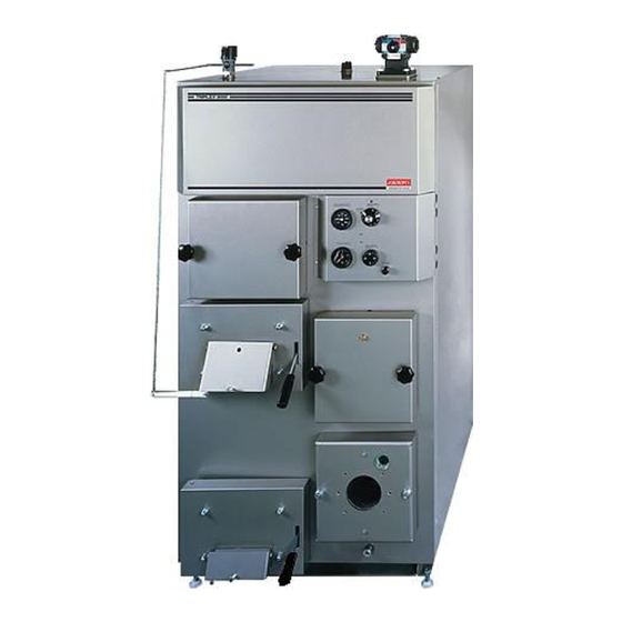
- Page 1 JASPI TRIPLEX Multifuel boilers I N S T A L L A T I O N A N D U S E R M A N U A L WWW.JASPI.UK J A S P I K N O W S H E A T I N G...
-
Page 2: Table Of Contents
Heating System ..................4 Electricity Connections ................4 BOILER INTRODUCTION ................5 Burner choice ....................5 Burner installation..................5 Burner adjustment ..................5 Wood side equipment installation ..............5 BOILER USAGE ..................6 Oil usage ....................6 Burning wood ....................7 General guidelines ..................8 UK TECHNICAL HELPLINE 01392 247 343 WWW.JASPI.UK... -
Page 3: Technical Data
100 °C ASSURANCE OF CONFORMITY WITH EC-STANDARDS This assurance applies to our manually-operated boilers functioning on solid fuel: JÄSPI Tupla, Triplex, ECOPUU, YPV 40. We assure that the abovementioned aggregata are in conformance with the essential safety requirements of the EC directive 97/23/EC, article 3, subsection 2.3. -
Page 4: Boiler Installation
A boiling prevention valve must be connected to the hot water coil to block overheating when wood is being burnt. Valve connection guidelines are shown in figure 2. Figure 2. Connecting the boiling prevention valve (e.g. Jäspi-TSK) to the driving water coil. 1. Valve group 2. Boiling prevention valve 3. Sensor WWW.JASPI.UK... -
Page 5: Heating System
MAX.240V/10A N L1 BURNER 10mm° 6mm° 11/R 21/S 31/T CUT-OFF THERMOSTAT N L1 1 2 3 4mm° 2,5mm° Signal lamp THERMOSTAT 12/U 22/V 32/W IMIT 2 BURNER TG 1 THERMOSTAT 6mm° BURNER HEATING ELEMENT CUT-OFF THERMOSTAT (SPL 3x2kW 230V) WWW.JASPI.UK... -
Page 6: Boiler Introduction
10 °C rise in exit gas temp erature. Wood part gear The traction control is installed in the traction control connection (nr. 5, figure 1) and the damper (nr. 7, figure 1) according to instructions. WWW.JASPI.UK... -
Page 7: Boiler Usage
(nr. 4, figure 3). The chambers are cleansed by removing and extracting the smut from the surfaces. After cleansing the exit gas control is replaced, the hatches are closed and power is switched back on. WWW.JASPI.UK... -
Page 8: Burning Wood
(nr. 1, figure 4) clean. The fire surfaces can be cleaned by brushing and scraping off the accumulated smut through the cleansing and filling hatches. Remove combustion residue through fire management hatch. Notice! The cleanness of the boiler’s fire surfaces is important to keep the high efficiency. WWW.JASPI.UK... - Page 9 Yellow white flame. Good air distribution. The stack No need to adjust burning. discharges light grey smoke. Dazzling white flame. Too much secondary air. The Decrease the amount of stack discharges white smoke. secondary air. WWW.JASPI.UK...
-
Page 10: General Guidelines
80 °C), the released temperature limiter can be retuned by pressing the temperature limiter (nr. 21 / 24, figure 1) button (strongly pressing with a narrow-tipped stick) on the control panel. WARRANTY Boiler warranty is two years, components’ warranty is one year. WWW.JASPI.UK...
Need help?
Do you have a question about the TRIPLEX and is the answer not in the manual?
Questions and answers