Subscribe to Our Youtube Channel
Summary of Contents for Jaspi PW
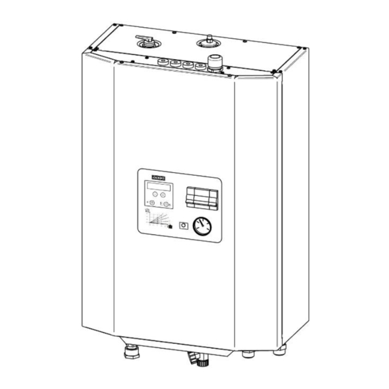
- Page 1 ELECTRIC BOILER INSTALLATION AND OPERATION MANUAL JASPI UK www.northmangroup.co.uk Telephone: 01392 247340 Email: info@northmangroup.co.uk JÄSPI KNOWS HOW TO CREATE WARMTH AND COMFORT...
-
Page 2: Table Of Contents
1. Contents 1. Contents 2. EC – Compliance 3. Operating Principle 3.1. Function Diagram 4. Technical Data 4.1. Equipment 4.2. Mounting to the Wall 5. Piping Installation 6. Electric Wiring 6.1. To Be Considered During Installation 6.2. External Connections to the Boiler Terminal Strip 6.3. -
Page 3: Ec - Compliance
The water tank is made of very the water temperature should not exceed the durable stainless steel alloy. permitted value, that is why PW is fitted with PW's circulating pump, expansion tank, safety a limiting thermostat to turn heating off when... -
Page 4: Function Diagram
3.1. Function Diagram... -
Page 5: Technical Data
4. Technical Data Dimensions (mm) (AxBxC) 660x470x250 Max. temperature 100°C Weight 35 kg Min. temperature 0°C Volume 3,5 l Design pressure 2.5 bar Supply: Max. power 12.2 kW - Outdoor temperature sensor Voltage 240 V, 1~ - 1 current transformer Frequency 50/60 Hz Backup power 4 kW Optional supply:... -
Page 6: Equipment
4.1. Equipment 1. Automatic heating system deaerator 11. Safety valve pipe R20 2. Safety relief valve 12. Drain and filling valve R15 3. Expansion tank 13. Return / Inlet R20 4. Immersion heating element 14. Outlet R20 5. Foam isolation 15. -
Page 7: Mounting To The Wall
4.2. Mounting to the Wall 1. Pull out two screws on top of the boiler (back side) and detach the bracket. 2. Mount the bracket to a reinforced wall with four screws. 3. Hang the boiler on the bracket hooks. 4. -
Page 8: Piping Installation
The maximum power of PW boiler (see picture 1, maximum power control) can be 6.1. To Be Considered During Installation The current transformers connected to the... -
Page 9: External Connections To The Boiler Terminal Strip
6.2. External Connections to the Boiler Terminal Strip Power wire 240 V, 50/60 Hz. Fuses and power wire determined for the unit according to the selected power rating. See table below for maximum power options. 6.3. Electric Boiler Power Table Step Power (kW) Current (A) -
Page 10: Electrical Diagram
7. Electrical Diagram... -
Page 11: Boiler Operation And Maintenance
PW operation is fully automated, thus pump shaft next to the deaeration screw ensuring easy service and maintenance. manually with a screwdriver (see picture 2.). -
Page 12: Heat Control With Outdoor Temperature Control
- x °C in fine adjustment board. example: If the selected curve is 25, heating If PW is introduced at the construction stage system water temperature is approx. 25°C, of the property and the floors are still drying when outdoor temperature is 0 °C. -
Page 13: Front Panel
9.1. Front Panel... -
Page 14: Screen Modes
9.2. Screen Modes PW automatic control unit screens. Normally the screen visible is basic screen state, but when the timer is set or the unit receives power limitation or trouble messages, the screen varies between basic screen state and additional screen state. -
Page 15: Settings
9.3. Settings Heating control basic settings, heating curve selecting, fine adjusting and temperature limits. -
Page 16: Temperature Decrease
9.4. Temperature Decrease This screen state is for selecting if a lower or higher heating setting is being used at a certain time of day. -
Page 17: Maintenance Menu
9.5. Maintenance Menu For the installer only! The service menu is for setting main fuse size of the property and max. power of the unit. -
Page 18: Troubleshooting
10. Troubleshooting - In case of any trouble first ensure that it is heating system may prevent water flow. not a case of power disruption or breakdown Check pump manual and section 8. of this of main / group fuses. boiler manual. -
Page 19: Resistance Values Of Boiler Sensors For Pcb 901497
By comparing the measured values the house (= current transformer measurement with the table below you can see the currents / location point) can be measured in PW by flowing through the current transformers in measuring the alternating current (AC) correspondence with voltages. -
Page 20: Installation Form
11. Installation Form The end user should ensure that the following form is completed after the installation of the unit. Unit number / year of manufacture Unit type Installer / company Date Wiring installer / company Date System operation / adjustment training Installer / company Date Installer settings prior to start-up...


Need help?
Do you have a question about the PW and is the answer not in the manual?
Questions and answers