Napoleon The Bayfield GDS25N Installation And Operating Instructions Manual
Natural gas
propane
Hide thumbs
Also See for The Bayfield GDS25N:
- Installation and operation instructions manual (28 pages) ,
- Installation and operation instructions manual (28 pages)
Table of Contents
Advertisement
Quick Links
CERTIFIED UNDER CANADIAN AND AMERICAN NATIONAL STANDARDS: ANSI Z21.88, CSA 2.33 FOR VENTED GAS FIREPLACE HEATERS.
GDS25N
NATURAL GAS
GDS25p
PROPANE
CERTIFIED FOR CANADA AND UNITED STATES USING ANSI/CSA METHODS.
SAFETY INFORMATION
WARNING
!
If the information in these instructions are
not followed exactly, a fire or explosion
may result causing property damage,
personal injury or loss of life.
- Do not store or use gasoline or other
flammable vapors and liquids in the vicinity
of this or any other appliance.
- WHAT TO DO IF YOU SMELL GAS:
Do not try to light any appliance.
Do not touch any electrical switch; do
not use any phone in your building.
Immediately call your gas supplier from
a neighbour's phone. Follow the gas
supplier's instructions.
If you cannot reach your gas supplier,
call the fire department.
-
Installation
and
performed by a qualified installer, service
agency or the supplier.
Phone (705)721-1212 • Fax (705)722-6031 • www.napoleonfireplaces.com • ask@napoleon.on.ca
$10.00
INSTALLER: LEAVE THIS MANUAL WITH THE APPLIANCE.
CONSUMER: RETAIN THIS MANUAL FOR FUTURE REFERENCE.
INSTALLATION AND
OPERATING INSTRUCTIONS
service
must
Wolf Steel Ltd., 24 Napoleon Rd., Barrie, ON, L4M 4Y8 Canada /
103 Miller Drive, Crittenden, Kentucky, USA, 41030
be
Serial No.
APPLY SERIAL NUMBER LABEL FROM CARTON
MODEL NO.
W415-0547 / D / 11.14.08
W415-0547 / D / 11.14.08
1
Advertisement
Table of Contents

Related Manuals for Napoleon The Bayfield GDS25N


Summary of Contents for Napoleon The Bayfield GDS25N
-
Page 1: Natural Gas
Serial No. agency or the supplier. MODEL NO. Wolf Steel Ltd., 24 Napoleon Rd., Barrie, ON, L4M 4Y8 Canada / 103 Miller Drive, Crittenden, Kentucky, USA, 41030 Phone (705)721-1212 • Fax (705)722-6031 • www.napoleonfireplaces.com • ask@napoleon.on.ca $10.00 W415-0547 / D / 11.14.08... -
Page 2: Table Of Contents
TABLE OF CONTENTS INtroDuctIoN WARRANTy DIMENSIONS GENERAL INSTRUCTIONS GENERAL INFORMATION CARE OF GLASS AND PLATED PARTS veNtING VENTING LENGTHS AND COMPONENTS SPECIAL VENT INSTALLATIONS 2.2.1 PERISCOPE TERMINATION 2.2.2 CORNER TERMINATION MINIMUM AIR TERMINAL LOCATION CLEARANCES DEFINITIONS ELbOW VENT LENGTHS HORIZONTAL TERMINATION VERTICAL TERMINATION VERTICAL THROUGH ExISTING CHIMNEy veNt INStallatIoN... -
Page 3: Introduction
1.0 INTrOduCTION WARNING • Do not operate heater before reading and understanding operating instructions. Failure to operate heater according to operating instructions could cause fire or injury. • Risk of fire or asphyxiation do not operate heater with fixed glass removed. •... -
Page 4: Warranty
NAPOLEON® warrants its products against manufacturing defects to the original purchaser only. Registering your warranty is not necessary. Simply provide your proof of purchase along with the model and serial number to make a warranty claim. NAPOLEON® reserves the right to have its representative inspect any product or part thereof prior to honouring any warranty claim. -
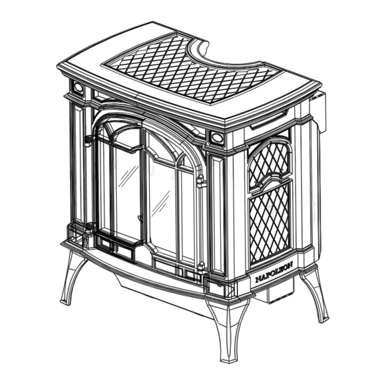
Page 5: Dimensions
dImENSIONS " fIGure 1.2a-c 7" DIA. 4" DIA. " " " " gENErAL INSTruCTIONS WARNING Provide adequate accessibility clearance for servicing and operating the fireplace. Provide adequate ventilation. Never obstruct the front opening of the fireplace. Objects placed in front of the fireplace must be kept a minimum of 48” from the front face of the unit. This product must be installed by a licensed plumber or gas fitter when installed within the commonwealth of Massachusetts. -
Page 6: General Information
gENErAL INFOrmATION The blower power cord must be connected into a properly grounded receptacle. The grounding prong must not be removed from the cord plug. for your SatISfactIoN, thIS Stove haS beeN teSt-fIreD to aSSure ItS operatIoN aND qualIty! Minimum inlet gas supply pressure is 4.5 inches water column for natural gas and 11 inches water column for propane. -
Page 7: Venting
2.0 vENTINg THIS HEATER USES A 4" EXHAUST / 7" AIR INTAKE VENT PIPE SYSTEM. Refer to the section applicable to your installation. For safe and proper operation of the heater follow the venting instruction exactly. Deviation from the minimum vertical vent length can create difficulty in burner start-up and/or carboning. - Page 8 16” fIGure 2.1a 24” MINIMUM REGARDLESS OF HORIZONTAL VENT LENGTH 25 5/8” 40FT fIGure 2.1c fIGure 2.1b 24” MAxIMUM 25 5/8” The maximum horizontal run with a 57” vertical rise immediately above the stove is 20 feet. W415-0547 / D / 11.14.08...
-
Page 9: Special Vent Installations
SpECIAL vENT INSTALLATIONS 2.2.1 pErISCOpE TErmINATION Use the periscope kit to locate the air termination above grade. The periscope must be installed so that when final grading is completed, the bottom air slot is located a minimum of 12" above grade. The maximum allow- able vent lengths depends on the heater, as illustrated. -
Page 10: Minimum Air Terminal Location Clearances
mINImum AIr TErmINAL LOCATION CLEArANCES fIGure 2.3 NOTE: Clearances are in accordance with local installation codes and the requirements of the gas supplier. TP - MINIMUM AIR TERMINAL LOCATION CLEARANCES W415-0547 / D / 11.14.08... -
Page 11: Definitions
dEFINITIONS For the following symbols used in the venting calculations and examples are: > - greater than > - equal to or greater than < - less than < - equal to or less than - total of both horizontal vent lengths (Hr) and offsets (Ho) in feet - combined horizontal vent lengths in feet - offset factor: .03 (total degrees of offset - 135°*) in feet - combined vertical vent lengths in feet... - Page 12 ) > (V Simple venting configuration (only one 45° and 90° elbow) See graph to determine the required vertical rise V for the required horizontal run H 90° 147” REQUIRED fIGure 2.6c VERTICAL RISE IN INCHES V 57” 45° 19 1/2” 2’...
-
Page 13: Vertical Termination
vErTICAL TErmINATION ) < (V Simple venting configurations. See graph to determine the required vertical rise V for the required horizontal run H fIGure 2.7a 45° HORIZONTAL VENT RUN PLUS OFFSET IN FEET H The shaded area within the lines represents acceptable values for H and V For vent configurations requiring more than one 45°... - Page 14 ) > (V Simple venting configurations. See graph to determine the required vertical rise V for the required horizontal run H fIGure 2.7c REQUIRED VERTICAL RISE IN 45° FEET V 90° HORIZONTAL VENT RUN PLUS OFFSET IN FEET H The shaded area within the lines represents acceptable values for H and V Example 2:...
-
Page 15: Vertical Through Existing Chimney
When installing the unit to this system, Duravent vent LINER components must be used. you must start with a Duravent adaptor, GDS924N, directly off the unit. The GDS924N is only available at your Napoleon® dealer. fIGure 2.8 40 FEET MAX. -
Page 16: Vent Installation
3.0 vENT INSTALLATION wALL ANd CEILINg prOTECTION WARNING Do not fill this space with any type of material. Do not pack insulation or combustibles between ceiling firestops. Always maintain specified clearances around venting and firestop systems. Install wall shields and firestops as specified. Failure to keep insulation or other materials away from vent pipe may cause fire. -
Page 17: Vertical Installation
3.1.2 vErTICAL INSTALLATION For venting clearances, see “MINIMUM CLEARANCE TO COMBUSTIBLES” section. GD36 FIRESTOP SLEEVE ASSEMBLY This application occurs when venting through a roof. Installation kits for various roof pitches are available from your Authorized dealer / distributor. See accessories to order specific kits required. -
Page 18: Horizontal Air Terminal Installation
3.2.1 hOrIzONTAL AIr TErmINAL INSTALLATION WARNING Follow the venting instructions exactly. All inner exhaust and outer intake vent pipe joints may be sealed using either red RTV high temp silicone sealant W573-0002 (not supplied) or black high temp mill pac W573-0007 (not supplied) with the exception of the fireplace exhaust flue collar which must be sealed using mill pac. -
Page 19: Vertical Air Terminal Installation
3.2.3 vErTICAL AIr TErmINAL INSTALLATION WARNING Maintain a minimum 2” space between the air inlet base and the storm collar. ● Fasten the roof support to the roof using the screws provided. The roof support is optional. In this case the venting is to be adequately supported using either an alternate method suitable to the authority having jurisdiction or the optional roof support. -
Page 20: Stove Vent Connection
STOvE vENT CONNECTION ● Attach the telescopic sleeve to the last section of rigid piping. Secure TELESCOPIC with screws and high temperature sealant W573-0002 (not supplied). #8x1/2" SLEEVE SELF DRILLING 2" OVERLAP SCREWS ● Install the 4” aluminium flexible liner through the 45° elbow to the stove. HI-TEMP Secure with 3 screws and flat washers. -
Page 21: Gas Installation
gAS INSTALLATION WARNING Risk of fire or explosion. Do not use open flame for testing. Support gas control when attaching pipe to prevent bending gas line. Always light the pilot whether for the first time or if the gas supply has run out with the glass door opened or removed. -
Page 22: Minimum Clearance To Combustibles
As long as clearance to combustibles is kept within the required distances, the most desirable and beneficial location for a Napoleon® stove is in the centre of a building, thereby allowing the most efficient use of the heat created. The location of windows, doors and the traffic flow in the room where the stove is to be located should be considered. -
Page 23: Minimum Mantel Or Shelf Clearances
mINImum mANTEL Or ShELF CLEArANCES WARNING Risk of fire, maintain all specified air space clearances to combustibles. Failure to comply with these instructions may cause a fire or cause the appliance to overheat. Ensure all clearances (i.e. back, side, top, vent, hearth, mantel, front, etc.) are clearly maintained. WARNING When the fireplace is rear vented, a mantel or shelf may be installed above the GDS25 at a minimum distance of 8”. -
Page 24: Finishing
5.0 FINIShINg CAST FrONT INSTALLATION ANd rEmOvAL WARNING Glass may be hot, Do Not touch glass until cooled. WARNING fIGure 5.1b 5.1.1 Lift the top cast piece off of the unit. fIGure 5.1a 5.1.2 Detach the front cast piece from SCREWS the side pieces by removing BRACKET... -
Page 25: Switch Functions
SwITCh FuNCTIONS MAIN ACCENT BURNER LIGHT SWITCH SWITCH CONTROL fIGure 5.3 LOgO pLACEmENT Remove the backing from the logo and position onto the control door as shown. 1/2” LOGO 1/2” fIGure 5.4 W415-0547 / D / 11.14.08... -
Page 26: Log Placement
LOg pLACEmENT WARNING Logs must be placed in the exact location in heater. Do not change from the proper log positions. Heater may not function properly. WARNING The logs are fragile and should be handled with care. It is not necessary to remove the cast front, however, this will make for a more simple log installation. In order to assemble the log set, the glass door must be removed, see “CAST FRONT / GLASS DOOR INSTALLATION AND REMOVAL”... -
Page 27: Optional Blower Installation
6.0 OpTIONAL BLOwEr INSTALLATION WARNING Risk of fire and electrical shock. WARNING Turn off the gas and electrical power before servicing this fireplace. Use only Wolf Steel approved optional accessories and replacement parts with this appliance. Using non-listed accessories (blowers, doors, louvres, trims, gas components, venting components, etc.) could result in a safety hazard and will void the warranty and certification. -
Page 28: Night Light Replacement
7.0 NIghT LIghT rEpLACEmENT comes equipped with our “Night Light”. WIRE NUT If in the event the lamp or lens needs to be replaced, follow these instructions. Disconnect the two wire leads at the wire nut. Remove the four screws securing the accent light assembly from the relief door. -
Page 29: Wiring Diagram
8.0 wIrINg dIAgrAm WARNING Always light the pilot whether for the first time or if the gas supply has ran out with the glass door open or removed. WARNING The on/off switch is located on the back of the GDS25 at the top right corner. For ease of accessibility, an op- tional remote wall switch or millivolt thermostat may be installed in a convenient location. -
Page 30: For Your Safety Read Before Lighting
9.0 OpErATION WARNING If you do not follow these instructions exactly, a fire or explosion may result causing property damage, personal injury or loss of life. Always light the pilot whether for the first time or if the gas supply has ran out with the glass door opened or removed. Assure that a continuous gas flow is at the burner before installing the door. -
Page 31: Adjustment
service technician or gas supplier. TO TURN OFF GAS 1. Turn off remote wall switch to the fireplace. 2. Turn off all electrical power to the fireplace if service is to be preformed. 3. Turn manual shutoff valve clockwise to off. Do no force. 10.0 mAINTENANCE WARNING... -
Page 32: Flame Characteristics
11.3 FLAmE ChArACTErISTICS It is important to periodically perform a visual check of the pilot and the burner flames. Compare them to the illustrations shown. If any flames appear abnormal call a service person. fIGure 11.3b fIGure 11.3a 11.4 pILOT INJECTOr ANd OrIFICE rEpLACEmENT WARNING Always light the pilot whether for the first time or if the gas supply has ran out with the glass door open or removed. -
Page 33: Replacement Parts
PILOT INJECTOR - LP W455-0071 PILOT INJECTOR - NG W720-0092 PILOT TUbE W100-0069 PILOT ASSEMbLy - NG W100-0093 PILOT ASSEMbLy - LP W385-0334 NAPOLEON LOGO W660-0009 ON/OFF SWITCH W387-0006 HALOGEN bULb 10W T320 W290-0108 TOP LENS GASKET W290-0109 bOTTOM LENS GASKET N402-0001... - Page 34 TErmINAL KITS part No. DeScrIptIoN GD175 wall termINal KIt bM6790 90° ELbOW - 7” DIAMETER GD222 TERMINAL ASSEMbLy bM67ADJ 30” TO 53” ADJUSTAbLE PIPE - 7” DIA W500-0077 FIRESTOP / WALL PLATE W020-0032 HARDWARE bRTC7 bRASS TRIM COLLAR bM6724 24” STOVE PIPE - 7” DIA W010-0300 10’...
- Page 35 ACCESSOrIES part No. DeScrIptIoN W690-0001 W690-0011b GS-65KT GDSLL-KT W175-0244 W175-0245 W175-0246 W175-0247 GD-301 W175-0001 GS331S GS-331F GS-331N ** For other available colours, add these letters to the base part number: colour finish Summer Moss - M Porcelain Majolica Brown - N Porcelain Winter Frost Porcelain...
- Page 36 W415-0547 / D / 11.14.08...
-
Page 37: Troubleshooting
13.0 TrOuBLEShOOTINg WARNING Always light the pilot whether for the first time or if the gas supply has fan out, with the glass door open or removed. SYMPTOM PROBLEM TEST SOLUTION Pilot will not light. Wiring. - Verify the “S” wire for the sensor and the “I” wire for the igniter are connected to the correct terminals (not reverse) on the module and pilot assembly. - Page 38 SYMPTOM PROBLEM TEST SOLUTION Continues to spark Poor grounding between pilot - Verify that the wire harness is firmly connected to module. and pilot lights, but assembly and gas valve. main burner will not light. Damaged pilot or dirty sensor rod. - Verify that the ceramic insulator around the sensor rod is not cracked, damaged, or loose.
-
Page 39: Service History
14.0 SErvICE hISTOry TP - SERVICE HISTORy W415-0547 / D / 11.14.08... -
Page 40: Notes
15.0 NOTES NOTES TP - NOTES W415-0547 / D / 11.14.08... - Page 41 NOTES TP - NOTES W415-0547 / D / 11.14.08...
Need help?
Do you have a question about the The Bayfield GDS25N and is the answer not in the manual?
Questions and answers