
Related Manuals for Omega RDXL4SD


Summary of Contents for Omega RDXL4SD
- Page 1 User’ s Guide Extended Warranty Program Shop online at omega.com e-mail: info@omega.com For latest product manuals: omegamanual.info MADE IN TAIWAN RDXL4SD 4-Channel Datalogger Thermometer...
- Page 2 ® Online Service Internet e-mail omega.com info@omega.com Servicing North merica: USA: OMEGA Engineering, Inc., One Omega Drive, P.O. Box 4047 ISO 9001 ertified Stamford, CT 06907-0047 USA Toll-Free: 1-800-826-6342 TEL: (203) 359-1660 FAX: (203) 359-7700 e-mail: info@omega.com Canada: 976 Bergar...
-
Page 3: Table Of Contents
T BLE OF CONTENTS Section Page 1. Features ............1 2. -
Page 4: Features
1. FEATURES • Type K/J/T/E/R/S, Pt 100 ohm, measurement with 4 channel display. • Simultaneously shows 4 channel display on the LCD. • Type K : -100 to 1300 °C. • Type J : -100 to 1200 °C. • Pt 100 ohm : -199.9 to 850.0 °C. •... -
Page 5: Specifications
2. SPECIFICATIONS 2-1 General Specifications Circuit Custom one-chip of microprocessor LSI circuit. Display LCD size: 52 mm x 38 mm LCD with green backlight ( ON/OFF ). Channels T1, T2, T3, T4, T1-T2. Sensor type Type K thermocouple probe. Type J/T/E/R/S thermocouple probe. PT 100 ohm probe Cooperate with an 0.00385 alpha coefficient, meet DIN IEC 751. - Page 6 Temperature Automatic temp. compensation for the Compensation type K/J/T/E/R/S thermometer. Linear Linear Compensation for the full range. Compensation Offset Available for Type K/J/T/E/R/S and Adjustment Pt 100 ohm. Probe Input Type K/J/T/E/R/S Socket 2 pin thermocouple socket. Pt 100 ohm : Ear phone socket. Over Indication Show "...
- Page 7 Power Current Normal operation ( w/o SD card save data and LCD Backlight is OFF) : Approx. DC 8.5 mA. When SD card save the data but and LCD Backlight is OFF) : Approx. DC 30 mA. * A If LCD backlight on, the power consumption will increase approx.
- Page 8 Type K/J/T/E/R/S Sensor Resolution Range Accuracy Type Type K 0.1°C -50.1 to -100.0°C ± ( 0.4 % + 1°C ) -50.0 to 999.9°C ± ( 0.4 % + 0.5°C) 1°C 1000 to 1300°C ± ( 0.4 % + 1°C) 0.1°F -58.1 to -148.0°F ±...
-
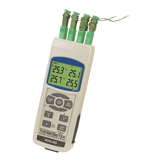
Page 9: Front Panel Description
3. FRONT PANEL DESCRIPTION Fig. 1 3-1 Display. 3-2 Power Button (ESC, Backlight Button) 3-3 Hold Button (Next Button) 3-4 REC Button (Enter Button) 3-5 Type Button (▲ Button, L Button) 3-6 T1-T2 Button (▼ Button, R Button) 3-7 SET Button (Time check Button) 3-8 Logger Button (OFFSET Button, Sampling time check Button) 3-9 T1,T2,T3,T4 input socket ( Type K, Type J ) 3-10 PT1 input socket (Pt 100 ohm) -
Page 10: Measuring Procedure
4. MEASURING PROCEDURE 4-1 Type K measurement 1) Power on the meter by pressing the “Power button” ( 3-2, Fig. 1 ) once. * After the meter is on, pressing the “Power button” once ( > 2 sec ) will turn off the meter. -
Page 11: T1-T2 Measurement
4-3 Pt 100 ohm measurement 1) All the measuring procedures are same as the Type K (section 4-1 ) except to select the Temp. Sensor type to “Pt” by pressing the “Type Button” (3-5, Fig. 1) once in sequence until the right down LCD display shows “Pt” text as : 2) Insert a Pt 100 ohm probe to PT1 input socket (3-10, Fig. -
Page 12: Data Hold
4-5 Data Hold During measurement mode, press the “Hold Button” (3-3, Fig. 1) once will hold the measured value & the LCD will display a “HOLD” symbol. Pressing the “Hold Button” once again will release the data hold function. 4-6 Data Record (Max., Min. reading) 1) The data record function records the maximum and minimum readings. -
Page 13: Lcd Backlight On/Off
4-7 LCD Backlight ON/OFF After power ON, the “LCD Backlight” will light automatically. While in measurement mode, press the “Backlight Button” (3-2, Fig.1) once will turn OFF the “LCD Backlight”. Press the “Backlight Button” once again will turn ON the “LCD Backlight”. -
Page 14: Auto Datalogger (Set Sampling Time 1 Sec)
5-2 Auto Datalogger (Set sampling time ≥ 1 second ) a. Start the datalogger Press the “REC Button (3-4, Fig. 1) once , the LCD will show the text “REC”, then press the “Logger Button” (3-8, Fig. 1), the “REC” will flash and the beeper will sound at the same time the measuring data along with the time information will be saved into the memory circuit. -
Page 15: Manual Datalogger (Set Sampling Time = 0 Sec)
5-3 Manual Datalogger (Set sampling time = 0 second) a. Set sampling time is to 0 second Press the “REC Button” (3-4, Fig. 1) once , the LCD will show the text “REC”, then press the “Logger Button” ( 3-8, Fig. 1 ) once, the “REC” will flash once and the Beeper will sound once, at the same time the measuring data along the time information and the Position no. -
Page 16: Check Sampling Time Information
5-5 Check sampling time information During the normal measurement mode (not execute the Datalogger), If you press “Sampling Button” (3-8, Fig. 1) once, the lower LCD display will present the Sampling time information in seconds. 5-6 SD Card Data structure 1) When using for the first time, the SD card will generate a folder: TMA01... -
Page 17: Saving Data From The Sd Card To The Computer
6. Saving data from the SD card to the computer (EXCEL software) 1) After executing the Data Logger function, remove the SD card from the “SD card socket” (3-18, Fig. 1). 2) Plug in the SD card into the Computer's SD card slot or insert the SD card into the “SD card adapter”, then connect the “SD card adapter”... -
Page 18: Advanced Setting
EXCEL graphic screen (for example) 7. ADVANCED SETTING Under do not execute the Datalogger function, press the “SET Button” (3-7, Fig. 1) for at least two seconds will enter the “Advanced Setting” mode. Pressing the “Next” Button (3-3, Fig. 1) will in sequence select the seven main functions, the lower display will show: dAtE.. -
Page 19: Set Clock Time (Year/Month/Date, Hour/Minute/Second)
Remark : While executing the "Advanced Setting" function, if you press the “ESC” Button (3-2, Fig. 1) once, you will exit the “Advanced Setting” function, the LCD will return to the normal screen. 7-1 Set clock time (Year/Month/Date, Hour/Minute/Second) When the lower display show " dAtE " 1) Press the “Enter”... -
Page 20: Decimal Point Of Sd Card Setting
7-2 Decimal point of SD card setting The numerical data structure default is “ . ” as the decimal. For example “20.6” “1000.53”. In certain countries (Europe) the “ , ” is used as the decimal point. For example “20,6” “1000,53”. When the lower display shows “dEC”... -
Page 21: Set Beeper Sound On/Off
7-4 Set beeper sound ON/OFF When the lower display shows “bEEP” 1) Use the “▲” Button " ( 3-5, Fig. 1 ) or “▼” Button " ( 3-6, Fig. 1 ) to select the upper value to " yES " or "... -
Page 22: Set Sampling Time
120, 300, 600, 1800,3600 seconds ). Remark : If selecting the sampling time to “0 second”, the RDXL4SD will be ready for manual Datalogging. 2) After the Sampling value is selected, press the “Enter” Button (3-4, Fig. 1) will save the setting function with default. -
Page 23: Power Supply From Dc Adapter
8. POWER SUPPLY from DC ADAPTER The meter can be powered by the DC 9V Power Adapter (optional). Insert the plug of Power Adapter into “DC 9V Power Adapter Input Socket” (3-13, Fig. 1). The meter will power ON (The power Button function is disabled). - Page 24 (9W 'D" Connector) Center Pin......Pin 4 (3.5 mm jack plug) Ground/shield..... Pin 2 2.2 K resistor Pin 5 The 16 digits data stream will be displayed in the following format : D15 D14 D13 D12 D11 D10 D9 D8 D7 D6 D5 D4 D3 D2 D1 D0 Each digit indicates the following status : Start Word When send the upper display data = 1...
-
Page 25: Offset Adjustment
RS232 FORMAT : 9600, N, 8, 1 Baud rate 9600 Parity No parity Data bit no. 8 Data bits Stop bit 1 Stop bit 11. OFFSET ADJUSTMENT 11-1 Type K/J/T/E/R/S offset adjustment 1) Set the function to Type K (or other type J/E/R/T/S). 2) Insert the probe to the T1 input socket (3-9, Fig. - Page 26 3) Pressing “Offset” button (3-8, Fig. 1) for at least two seconds then release, the display will show : Pt 1 Pt 2 4) If you wish to make the offset adjustment for Pt 1, please insert the probe to PT1 input socket. Press the “L” button (3-5, Fig.
- Page 27 W RR NTY/DISCL IMER OMEG ENGINEERING, INC. warrants this unit to be free of defects in materials and workmanship for a period of 13 months from date of purchase. OMEG ’s Warranty adds an additional one (1) month grace period to the normal one (1) year product warranty to cover handling and shipping time.
- Page 28 Where Do I Find Everything I Need for Process Measurement and Control? OMEG …Of Course! Shop online at omega.com TEMPER TURE Thermocouple, RTD & Thermistor Probes, Connectors, Panels & Assemblies Wire: Thermocouple, RTD & Thermistor Calibrators & Ice Point References Recorders, Controllers &...
Need help?
Do you have a question about the RDXL4SD and is the answer not in the manual?
Questions and answers