
Related Manuals for Omega CL940A


Summary of Contents for Omega CL940A
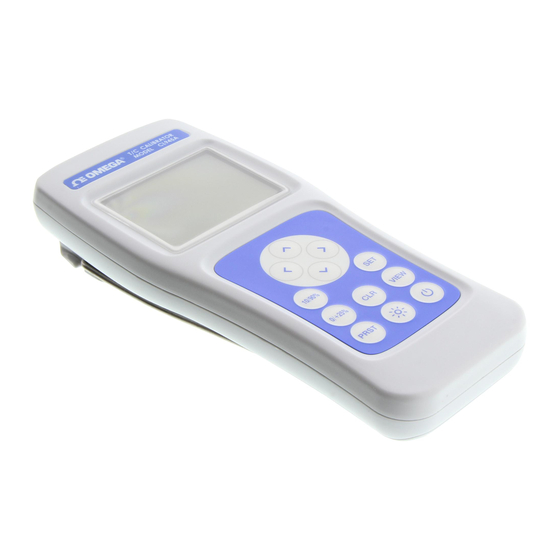
- Page 1 User’ s Guide Shop online at omega.com e-mail: info@omega.com For latest product manuals: www.omegamanual.info CL940A, CL945A Digital Temperature Calibrator–Thermometer...
- Page 2 Where Do I Find Everything I Need for Process Measurement and Control? OMEGA… Of Course! Shop online at omega.com TEMPERATURE M U Thermocouple, RTD & Thermistor Probes, Connectors, Panels & Assemblies M U Wire: Thermocouple, RTD & Thermistor M U Calibrators & Ice Point References M U Recorders, Controllers &...
-
Page 3: Table Of Contents
Table of Contents ABLE OF ONTENTS 1. Instrument Description ............. 1-1 Specifications ..............1-1 OMEGA Family of Thermometers ........... 1-5 2. Preparation for Use ..............2-1 General Information ............2-1 Feature Overview ............... 2-1 Safety Notices and Information ..........2-2 Unpacking and Inspection ............ -
Page 4: Instrument Description
Instrument Description 1. I NSTRUMENT ESCRIPTION Specifications Source/Measure ±0.003% * [R ] ± 5 V 18° 28°C EADING µ Accuracy 0.01°C 999.99°C 0.1°C ≥ 1000°C ESOLUTION UP TO ANGE ±0.15°C UNCTION RROR (0.1/0.01) IGIT ESOLUTION WITH ACKLIGHT AND ISPLAY FUNCTION NNUNCIATORS 28°C (64.4 82.4°F) | CJC error included... - Page 5 Instrument Description -240 to -150 ±1.2 to ±0.4 -150 to -100 ±0.4 -240°C – 1000°C -400°F – 1832°F -100 to 20 ±0.3 20 to 1000 ±0.2 310 to 595 ±1.8 to ±1.0 595 to 830 ±0.9 310°C – 1820°C 590°F – 3308°F 830 to 965 ±0.7 965 to 1820...
- Page 6 Instrument Description 0°C to 1395°C 0 to 1395 ±0.3 32°F to 2543°F -200 to -90 ±0.6 to ±0.4 -100 to -40 ±0.4 J-DIN -200°C - 900°C -40 to 655 ±0.3 -328°F – 1652°F 655 to 665 ±0.4 665 to 900 ±0.3 ±0.8 to ±0.5 -200 to -75...
- Page 7 Instrument Description Input Current ±50 nA maximum Maximum Common 42 V peak to earth 1 V p-p between T1 and T2 Mode Voltage Low Resistance Load Less than 5µV change in output with a 100KΩ resistance Operating Environment Operating Temp -20 to 55 °C -4 to 131 °F Storage Temp...
-
Page 8: Omega Family Of Thermometers
Instrument Description OMEGA Family of Thermometers HH911T Thermocouple Thermometer, Single Input Thermocouple Thermometers HH912T Thermocouple Thermometer, Dual Input HH931T Data Thermometer, Single Input Data Thermometers HH932T Data Thermometer, Dual Input... - Page 9 General Information This manual provides operating instructions and maintenance information for two calibrator instruments, CL940A and CL945A. These instruments are high performance calibrator- thermometers capable of simulating and measuring a wide-variety of sensors. In addition, features such as high accuracies, preset storage, ramp, step and transfer modes further enhance their versatility.
-
Page 10: Preparation For Use
Preparation for Use Safety Notices and Information Read this Operation Manual thoroughly before using the instrument to become familiar with its operations and capabilities. Visually inspect instrument before using. Do not use if unit appears damaged or with any part of the case removed. - Page 11 Preparation for Use CAUTION RISK OF INCORRECT READING Do not use when AC or DC voltages in excess of 1V exist between thermocouple channels (on instruments with more than one channel). Excessive voltage could result in an incorrect reading, or in more extreme cases, a blown fuse that will result in incorrect readings and need for repair. RISK OF INSTRUMENT DAMAGE Only replace batteries with size AA (IEC LR6, ANSI 15).
-
Page 12: Unpacking And Inspection
Use the original packing materials if reshipment is necessary. If any dents, broken, or loose parts are seen, do not use the equipment. Notify OMEGA immediately. Check that all items are present. If any items are missing, notify OMEGA immediately. -
Page 13: Initial Power On
Gasket Figure 1: Battery Installation Initial Power ON OMEGA’s 900 Series Calibrator Thermometers are designed for easy operation, while still providing a feature-rich experience via the intuitive user interface. To get started follow these steps: Perform Section 2.5, Battery Installation and Replacement;... - Page 14 Preparation for Use arrows always change a value. The arrows position the cursor or will act to select only when changing Thermocouple type, desired digit or changing the mode. Momentarily (do not hold) press to save your selection and move to the next parameter;...
-
Page 15: Operating Instructions
Operating Instructions 3. O PERATING NSTRUCTIONS Keypad Functions The instrument keypad is a twelve (12) key, sealed membrane keypad. Each key provides audible and tactile user feedback when pressed. Key functions are described in Figure 2 below. Power instrument ON or OFF and exits Key Lock mode. -
Page 16: Lcd Display
Operating Instructions approximately 1.5 seconds. Throughout this Operation Manual, the press and hold sequence is indicated by the key designator followed by the subscript (1.5s). For instance, (1.5s) indicates that the key should be pressed and held for 1.5 seconds, then released to access the desired function. - Page 17 Operating Instructions Range is currently displayed, the MAX minus MIN value. Instrument is displaying the Average reading over the last 1000 measurement cycles. Step Function: There are 10 equal steps between 0°C and Span. Source continuously steps up and down. There is a 5 second dwell time on each step. MAX statistic.
-
Page 18: Setup Menu
Operating Instructions Setup Menu Key designators followed by (1.5s), e.g. (1.5s) , indicate that the key should be pressed and held for 1.5 seconds, then released to access the desired function. Measurement settings are configured in the Setup Menu. Press (1.5s) to access the Setup Menu. - Page 19 Operating Instructions °C °F ETUP ENU CHOICES FOR ARAMETER VAILABLE ALUES Thermocouple Type K, J, T, E Temperature and °C, °F, mV voltage Units Probe Offset ±0.1 ° increments Open Lead detection On / Off (old) Source (SourC) On / Off Set 100% Level If on –...
-
Page 20: View Modes And Statistics
Operating Instructions Set 0% Level Range Hi mV (default) [-15mV to +85mV] Range (rAnGE) Range Lo mV (mV flashing) [-15mV to +35mV] blinking Manual “__ __ __ __” Fast Ramp If on – Set Mode Slow Ramp Step Transfer Low range is for calibration verification only. Figure 5 If no key is pressed for 10 seconds, the instrument will save the current configuration and exit the Setup Menu. -
Page 21: Auto-Power Off
ODEL OURCE TATISTIC EQUENCE HANNEL Value from CL940A/ STDEV source CL945A channel Figure 7: Statistics Sequence If the instrument records invalid measurement data during the statistics session such as an over-range, under-range, or open input value, ————— will be displayed for each affected statistic result. -
Page 22: Backlight And Backlight Timeout
Operating Instructions Backlight and Backlight Timeout The instrument includes an LED backlight feature to ensure measurement data can be easily read in low-light conditions. To activate the backlight, press Once the backlight is activated, it will automatically turn off after 30 seconds if no key is pressed to preserve battery life. -
Page 23: Trend Indicators
Operating Instructions While in any of the Operating Modes above, unless Auto Power Off was disable, the instrument will automatically turn off if no key is pressed for 20 minutes. Trend Indicators Trend indicators provide a visual representation of the measurement’s stability, and are provided for the Read channel. - Page 24 Operating Instructions Probe offset rounding errors may occur if temperature units are changed while a probe offset is active. When using a probe offset, verify and if necessary correct the programmed probe offset after changing temperature units. To set the probe offset when using an un-calibrated temperature probe: Connect the temperature probe to the Read Channel of the instrument;...
-
Page 25: Open Lead Detection Enable/Disable
Operating Instructions Press to save the offset value and proceed to Open lead detection or press to save the offset value and exit the Setup Menu. Alternatively, to disregard the new offset value and exit the Setup Menu, press OFFSET is displayed at the top-left of the LCD display. Open Lead Detection Enable/Disable Open Lead Detection allows the unit to detect if a thermocouple probe is connected to the thermometer. -
Page 26: Presets: Save, Recall And Erase
Operating Instructions Pressing (1.5s) deletes all measurement data currently saved in the instrument’s internal memory except for Presets. From the Setup Menu, press to disregard changes to the current parameter value and exit the Setup Menu. Presets: Save, Recall and Erase There are 20 presets in the instrument numbered 0 –... -
Page 27: Invalid Measurement Indications
Operating Instructions momentarily. The location is now empty and will not appear with any of the saved presets when trying to recall a preset. The preset number just erased will still appear on the LCD until moved from that preset number. Once moved to a different preset, it will no longer appear when trying to recall a preset. -
Page 28: Service Information
Service Information 4. S ERVICE NFORMATION Inspection and Cleaning To extend the life of the instrument, inspect and clean the instrument regularly. Inspect the instrument for any significant abrasions, cuts, cracks, dents, or other signs of damage on the case, keypad, and display lens. Inspect the connectors for breaks, dirt, or corrosion. Ensure all screws are securely fastened, and if equipped, that the tilt stand/magnet/hanger is in good condition and locks into position properly. - Page 29 Service Information Figure 11 High range: (in mV) Low range: (in mV) [-15mV to +85mV] [-15mV to +35mV] -13.000 -13.000 -10.000 -10.000 0.000 0.000 5.000 10.000 20.000 30.000 80.000 33.000 83.000 Figure 12 Use the Instrument Verification Data Sheet, Appendix C to verify the measurements in Figure 12 above.
- Page 30 13. To verify the Cold Junction Compensation, (CJC) of the Source, (Channel 1) and Read, (Channel 2). 14. Place the CL940A in a Controlled Environment along with an accurate thermometer for one hour to stabilize. Compare CJC readings with the reference thermometer reading.
- Page 31 Service Information Insulated container with lid for controlled Position accurate thermometer sensor in environment middle of MTC 1 and 2 as shown above Figure 13 15. Calculate the Lower and Upper limits: First add a factory determined offset of 0.06°C to the “Standard” value, then add/subtract 0.11°C from the result. For example: the thermometer reading stabilized at 23.82°C;...
- Page 32 Service Information Connect the Positive of the Source and Read channels to the positive input of the DMM. Connect the negative of the Source and Read channels to the negative input of the DMM. Press UUT to turn the UUT on. Disable the Auto-Power Off press (1.5s) Do not apply voltages greater than 83 mV DC to the UUT inputs.
-
Page 33: Troubleshooting
Troubleshooting OMEGA’s digital handheld thermometers are designed and built to provide years of uninterrupted use. In the event the instrument malfunctions or does not perform as expected, helpful troubleshooting tips are provided below. Figure 14 below lists some of the more common issues and their resolutions. -
Page 34: Diagnostic Routines And Error Codes
Service Information YMPTOM ESCRIPTION ESOLUTION Observe display trend indicators Temperature probe has not and wait for stable measurement stabilized (see Section 3.8 Trend Indicators) Set the thermocouple type as Instrument is set to the wrong appropriate for the attached thermocouple type for the probe (see Section 3.3, Setup attached probe Menu) -
Page 35: Statement Of Calibration
This instrument has been inspected and tested in accordance with specifications published by OMEGA, Inc. OMEGA, Inc. certifies the above listed instrument has been inspected and calibrated and meets or exceeds all published specifications and has been calibrated using standards whose accuracies are traceable to the... - Page 36 Appendices A. R EQUIRED QUIPMENT (2-S QUIPMENT UNCTION ANGE PECIFICATION IGMA DC Voltage -13mV to 83 mV ± (30 ppm of reading + 9 ppm of range) Measurement Measure Calibrated ambient temperature temperature 18°C to 28°C ±40 mK (.04°C) measurement during cold device junction test.
-
Page 37: Expanded Instrument Uncertainties
Appendices B. E XPANDED NSTRUMENT NCERTAINTIES All uncertainty specifications for all charts are K = 2 unless otherwise noted. - Page 38 Appendices Following graphs show total uncertainty in degrees C (k=2), with operating condition between 18-28 °C unless otherwise noted. B-ii...
- Page 39 Appendices Thermocouple Type K B-iii...
- Page 40 Appendices B-iv...
- Page 41 Appendices Thermocouple Type J...
- Page 42 Appendices B-vi...
- Page 43 Appendices Thermocouple Type T B-vii...
- Page 44 Appendices B-viii...
- Page 45 Appendices Thermocouple Type E B-ix...
- Page 46 Appendices...
- Page 47 Appendices Thermocouple Type B 1.6000 1.4000 1.2000 1.0000 0.8000 0.6000 0.4000 0.2000 0.0000 18C - 28C -20C Temp Uncertainty (C), k=2 +55C Temp Uncertainty (C), k=2 B-xi...
- Page 48 Appendices B-xii...
- Page 49 Appendices Thermocouple Type N 2.0000 1.8000 1.6000 1.4000 1.2000 1.0000 0.8000 0.6000 0.4000 0.2000 0.0000 18C - 28C -20 Temp Uncertainty (C), k=2 +55 Temp Uncertainty (C), k=2 B-xiii...
- Page 50 Appendices B-xiv...
- Page 51 Appendices Thermocouple Type R B-xv...
- Page 52 Appendices B-xvi...
- Page 53 Appendices Thermocouple Type S B-xvii...
- Page 54 Appendices B-xviii...
- Page 55 Appendices Thermocouple Type G B-xix...
- Page 56 Appendices B-xx...
- Page 57 Appendices Thermocouple Type C B-xxi...
- Page 58 Appendices B-xxii...
- Page 59 Appendices Thermocouple Type D B-xxiii...
- Page 60 Appendices B-xxiv...
- Page 61 Appendices Thermocouple Type P B-xxv...
- Page 62 Appendices B-xxvi...
- Page 63 Appendices Thermocouple Type L B-xxvii...
- Page 64 Appendices B-xxviii...
- Page 65 Appendices Thermocouple Type U B-xxix...
- Page 66 Appendices C. I NSTRUMENT ERIFICATION HEET Model: Serial Number: IMITS OF RROR OWER PPER XPANDED IMIT IMIT ARAMETER ETPOINT EASUREMENT ESULT NCERTAINTY Source DC Volts Channel 1 High Range -13mV to 83 mV -13 mV -13 mV -13.00498 mV -12.99502 mV 0.00194 mV -10 mV -10 mV...
- Page 67 Appendices Low Range -13mV to 33 mV -13 mV 0.005 mV 0.00194 mV -10 mV 0.005 mV 0.00192 mV 0 mV 0.0046 mV 0.0019 mV 10 mV 0.0049 mV 0.00192 mV 30 mV 0.00545 mV 0.0021 mV 33 mV 0.00545 mV 0.00214 mV IMITS OF RROR...
- Page 68 OMEGA be liable for consequential, incidental or special damages. CONDITIONS: Equipment sold by OMEGA is not intended to be used, nor shall it be used: (1) as a “Basic Component” under 10 CFR 21 (NRC), used in or with any nuclear installation or activity;...
- Page 69 For Other Locations Visit omega.com/worldwide CL940A Rev. A M5725/0219 The information contained in this document is believed to be correct, but OMEGA accepts no liability for any errors it contains, and reserves the right to alter specifications without notice.
Need help?
Do you have a question about the CL940A and is the answer not in the manual?
Questions and answers