Table of Contents
Advertisement
Advertisement
Table of Contents

Related Manuals for Hootoo HT-IP006N


Summary of Contents for Hootoo HT-IP006N
- Page 1 HT-IP006N Manual Book...
-
Page 2: Table Of Contents
Security Solutions Partner CONTENTS 1 WELCOME..................................3 1.1 F ........................................3 EATURES 1.2 P ......................................3 ACKING 1.3 P ....................................... 4 RODUCT IEWS 1.4 PC S ..................................5 YSTEM EQUIREMENTS 1.5 H ..................................5 ARDWARE NSTRUCTION 1.6 S ..................................5 OFTWARE NSTALLATION 2. -
Page 3: Welcome
Security Solutions Partner 1 WELCOME This is an integrated wireless IP Camera. It combines a high quality digital Video Camera with network features and a powerful web server. You can access this camera from anywhere on your local network or over the Internet. -
Page 4: Product Views
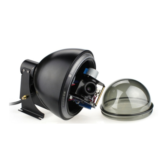
Security Solutions Partner 1.3 Product Views 1.3.1 Front View Figure 1.1 1.3.2 Cable Interface Figure 1.2 Audio Output: The jack is used to plug external speakers or audio output devices. Audio Input: The jack is used to plug external microphones or audio input devices. I/O Alarm Pin: 1 Alarm input (GND), 2 Input, 3 Output A, 4 Output B Network Interface: RJ-45/10-100 base T Network indicator: The green LED will be on when the network is connected. -
Page 5: Pc System Requirements
Security Solutions Partner default settings. (Please keep the power on when using RESET) Power: DC 12V/2A power supply 1.4 PC System Requirements System configuration requirements: (Example for viewing four IPCAM) CPU: 2.06GHZ or above Memory: 256M or above Network Card: 10M or above Display Card: 64M or above memory Recommendable Operating System: Windows 2000/ XP/ Vista/ 7 1.5 Hardware Instruction... - Page 6 Security Solutions Partner Figure1.5 Figure1.6 Figure1.7 After this done, the icon “IP Camera Tool” will be displayed on your desktop automatically .
-
Page 7: Software Operation
If you turn the lens, it may cause incorrect focus and vague images. Do not turn the Pan/Tilt by force, it may cause damage to internal components of the Pan/Tilt. For firmware upgrading, please always contact us first via support@hootoo.com. 2. SOFTWARE OPERATION 2.1 IP Camera Tool... - Page 8 Security Solutions Partner choose the prompt and click the right mouse, choose Network Configuration to set the static IP address of the Camera to the same subnet as LAN. (Figure 2.2) NOTE: If it shows” Subnet doesn’t match, double click to change!”, you can also choose ”Obtain IP from DHCP Server”...
-
Page 9: Network Configuration
Security Solutions Partner Figure2.0 2.1.1.2 Network Configuration In this page, you can configure the Network parameter. Figure2.1 Obtain IP from DHCP server: If clicked, the device will obtain IP from DHCP server. In other words, the camera will have a dynamic IP. (Make sure the Router which the camera is connected to has DHCP function and DHCP is enabled). -
Page 10: Upgrade Firmware
Security Solutions Partner Gateway: Make sure it is in the same subnet with your PC’s IP address. Gateway is the LAN IP of your router. DNS Server: IP address of IPS network provider. You can also set it’s the same as the Gateway. NOTE: You can find the Subnet Mask, Gateway, DNS Server from your router, or check the local connection status of your computer to get all the parameters. -
Page 11: Camera Login
Security Solutions Partner Check the IP Camera Tool Version and IP Camera ActiveX Control Version here. 2.2 Camera Login You can access the camera through IP Camera Tool or IE, Firefox, Safari, Google Chrome or other browsers. 1. Double click the IP address of the IP Camera listed (Figure 1.8). The default browser you use will run automatically and open the camera login interface. -
Page 12: For Ie Browser
Security Solutions Partner Figure 2.6 (1) Active Mode (For IE Browser): available in IE6.0 or above (2) “Server Push Mode”: available in Firefox, Safari, and Google Chrome browser. (3) “Sign in mobile phone”: available for Mobile phones 2.3 For IE Browser Choose Active Mode (For IE Browser), and sign in Figure 2.7 The first time you login to the camera, you might get the ActiveX prompt as the picture above, please click the... - Page 13 Security Solutions Partner Figure2.8 Figure 2.9 Note: If there is still no live video after running ActiveX, and a red cross shows in the center of the screen, or even just a black screen, please try to enable the ActiveX options in IE security settings. Please do the follow steps: 1.
- Page 14 Security Solutions Partner Figure3.0 Figure 3.1 In addition: you can also click “Start” menu->“Internet Explorer”, choose “Internet attributes “ to enter, or via “Control Panel” ->“Internet Explorer”, enter to Security setting. If ActiveX is running, but you still could not see live video, please try using another port number. Don’t use port 80, use other ports such as 128, 1008 etc.
-
Page 15: For Safari, Firefox, Google Browser
Security Solutions Partner Figure 3.2 NOTE: Make sure that the firewall or anti-virus software doesn’t block the software or ActiveX. If you couldn’t see live video, please close your firewall or anti-virus software, and try again . 2.4 For Safari, Firefox, Google Browser Choose Server Push Mode (For Safari, Firefox, Google Browser), and sign in Server Push Mode doesn’t support ActiveX, so some functions are not available, such as Play, Stop, Record, Audio, Talk etc. -
Page 16: For Mobile Phone
Security Solutions Partner 2.5 For Mobile Phone Choose Sign in mobile phone, and sign in. Mobile phone doesn’t support ActiveX, only some basic functions can be available in this mode. It supports most smartphones with a 3G/4G connection. Usually, if the mobile phone supports network video, then it can work with our IP Camera. - Page 17 Security Solutions Partner Figure 3.5 Channels: Our IE software supports 9 channels total. Clicking can get different windows. Click this one, you can view the main channel of the camera. Click this one; you can view 4 Channels of cameras that are connected, from CH1 to CH4. Click this one;...
-
Page 18: Osd Settings
Security Solutions Partner OSD Settings: Figure 3.6 OSD: Means “On-Screen Display”, click “Audio video” > “OSD”, set display date and time on the video. Disabled: Click this one, means clear the OSD. Color: Can set the OSD text color as black, yellow, red, white, blue etc. Add time stamp on record: Click this, there will be time OSD on record video files. - Page 19 Security Solutions Partner Rate and Resolution: Rate: Set video framerate here, from “full-speed to 1fp/5s”. (Figure 3.8) Resolution: Set the resolution to be 160*120/ VGA(640*480)/ QVGA (320*240). (Figure 3.9) NOTE: When doing recording, Rate and Resolution parameter settings is very helpful for getting small sized recording files, the lower parameter to get the smaller file.
-
Page 20: For Operator
Security Solutions Partner NOTE: For visitor, if you click other menus which visitor don’t have the right to operate it, there will be a pop-up of the login interface (Figure 2.6), please input the user name / password for at least 3 times to login again. 2.8 For Operator When logged in as Operator, you can enter the IP Camera with Operator mode. - Page 21 Security Solutions Partner Reversal: Click this icon to see the reversal image. Click again, will be back to normal. Mirror: Click this icon to see the mirror image. Click again, will back to normal. NOTE: You can choose Reversal and Mirror function when you set up the camera in a special position. Mode, Bright, Contrast Settings ...
-
Page 22: For Administrator
Security Solutions Partner RECOMMENDATION: Image PT function: Image PT function is recommended, you can control the camera direction on the live video. Double click the right mouse on the live video to enable this function, and you will see a white & transparent arrow on the live video, left click to control direction, eight directions are available. -
Page 23: Multi-Device Settings
Security Solutions Partner Figure 4.6 3.1 Multi-Device Settings Multi-Device Settings This camera can support max. 9 channels device at the same time. 3.1.1 Set Multi-Device in LAN In the Multi-Device Settings page, you can see all devices searched in LAN. The 1st device is the default one. You can add more cameras listed in LAN for monitoring. - Page 24 Security Solutions Partner Figure 4.7 Click Live Video and then select to see four channels, or click to see nine channels. Figure 4.8...
- Page 25 Security Solutions Partner Figure 4.9 3.1.2 Set Multi-Device for WAN If you want to view your cameras from the internet, you have to add these devices by DDNS domain name. Make sure all these cameras you want to add have been set to DDNS successfully. (View 3.7 DDNS Service Settings) Login the first camera by DDNS domain name and port, this camera will be set as the host camera.
- Page 26 Security Solutions Partner Submit. NOTE: The Alias is optional; you can set the alias as you desire. The Host must be the camera’s DDNS domain name, and without “http://”, it’s not the LAN IP address. If you have several cameras, you can use the same DDNS domain name, just set different port numbers for each different camera.
-
Page 27: Upgrade Device Firmware
Security Solutions Partner Figure 5.2 Click Live Video and then selec t to see four channels, or to see nine channels. In this case, you can see all the cameras from a remote position by internet, for example, if you are on the business trip, you can use the first camera’s (Host camera) DDNS to view all the devices via internet Figure 5.3 3.1.3 Upgrade Device Firmware... -
Page 28: Network Settings
Security Solutions Partner 3.1.4 Restore Factory Settings Click Restore Factory Settings, a pop-up will prompt, select OK, all the parameters will be returned to factory settings, and the device will reboot. Figure 5.5 3.1.5 Reboot Device Click Reboot the device, a pop-up will prompt, select OK, then the device will reboot Figure 5.6 3.2 Network Settings Click Network, will pop-up the prompt as below:... - Page 29 Security Solutions Partner Figure 5.7 If you don’t know Subnet Mask, Gateway, DNS Server, please check the Local Area Connection Status of your computer; it contains all this information, steps as below: 1. Control PanelNetwork ConnectionsLocal Area Connections Support Details 2.
-
Page 30: Wireless Lan Settings
Security Solutions Partner If you don’t know the DNS Server, you can set it the same as Gateway. If the router supports DHCP function, you can choose “Obtain IP from DHCP Server” to get dynamic IP. Figure 6.0 Http Port: In most cases, you can leave this value as default, if your Internet Service Provider blocks this port, you may change it to another port number such as 85. - Page 31 Security Solutions Partner Figure 6.3 Figure 6.4 Figure 6.5...
-
Page 32: Adsl Settings
Security Solutions Partner 3.5 ADSL Settings When connected to the Internet through ADSL directly, you can enter the ADSL username And password obtained from ISP. Figure 6.7 3.6 UPnP Settings Click UPnP Settings to choose Using UPnP to Map Port: ... - Page 33 Security Solutions Partner Figure 7.0 There are 2 options: Manufacturer’s DDNS: This domain is provided by manufacturer. Third Party DDNS: This domain is provided by the 3 party, such as Dyndns, Oray, 3322 etc. Figure 7.1 Third Party DDNS If you use a third party DDNS, please choose the server you use, such as “3322.org” or “dyndns.org” as below: Figure 7.2 Figure 7.3 You have to register an account first, keep the user, password, host, then input it.
- Page 34 Security Solutions Partner Change the camera’s port. The default port of the camera is “80”, please change “80” to any other one you like, such as “81”, “100”, “8091” etc. Click “OK”, the camera will reboot, wait about 30 seconds . Figure 7.4 Make sure the “Subnet Mask”, “Gateway”, “DNS Server”...
- Page 35 Security Solutions Partner BELKIN: 1. Login the router. 2. Choose “Firewall”, select “Virtual Servers” 3. Input the port (except 80) and IP address, then click save. NOTE: The port and IP address should be the same as Camera. Figure 7.6 DLINK: 1.
-
Page 36: System Settings
Security Solutions Partner Step: “Login”>”System”>”Device Info”: Figure 7.8 Figure 7.9 3.8 System Settings Figure 8.0 3.8.1 Device Info You can find the information about Device ID, Firmware Version, Embedded Web UI Version, Alias, Alarm Status, DDNS Status, UPnP Status and MSN status. -
Page 37: Alias Settings
Security Solutions Partner Figure 8.1 3.9 Alias Settings Default device name is anonymous. You set any new name for your camera here, then click Submit . Figure 8.2 3.10 Date &Time Settings Set the date and time for your camera. Choose the Clock Time zone of your country. -
Page 38: Users Settings
Security Solutions Partner Figure 8.4 3.11 Users Settings Eight accounts are acceptable for this system. Here you can set the user names and password as Administrator, Operator or Visitor, the permission for them as below: Visitor: In this mode, you can only view. (Details 2.7) ... -
Page 39: Ptz Settings
Security Solutions Partner 3.12 PTZ Settings Figure 8.6 1. Go center on boot: The camera will rotate to the center automatically when it starts 2. PT speed: Set Pan / Tilt speed 3. Upward patrol speed: Set the speed of cruising upward 4. - Page 40 Security Solutions Partner (1) Backup: Backup IP Camera settings, if you want to save all the current settings that you have set already, you can click Submit, then all the parameters you set will store as a parameters bin file. (2)Restore: Restore IP Camera settings, if you want to change the camera’s settings to a certain status which has a backup, click Browse to load the bin file, then Submit it.
-
Page 41: Other Settings
Security Solutions Partner Run your MSN, open the chat dialog, type in the word “url?”, after a few seconds, you will get a reply for the remote access ip address for this ip camera. 3.15 Other Settings Figure 9.0 Here you can configure some additional functions such as Motion Detection, Alarm, IO Linkage, Schedule, FTP Upload, Alarm Mail Alert, Record Path etc. - Page 42 Security Solutions Partner Figure 9.1 Sender: Make sure the sender mailbox server provider support SMTP, and the mailbox should not enable SSL or TSL encryption too. Receiver: Here you can set four receivers. For receiver, there is no SMTP limitation. SMTP Server: The sender’s SMTP Server.
-
Page 43: Ftp Service Settings
Security Solutions Partner again 6) The receiver is denied by the server. Maybe because of the anti-spam privacy of the server 7) The message is denied by the server. Maybe because of the anti-spam privacy of the server 8) The server does not support the authentication mode used by the device Report Internet IP by Mail: If selected, you will receive emails which contain the camera’s internet IP. -
Page 44: Alarm Service Settings
Security Solutions Partner Click Submit after these settings. Then click Test. You will see the following picture. Figure 9.5 If it prompts error information as follows. 1) Cannot connect to the server. Please check FTP Server is correct or not. 2) Network Error. - Page 45 Security Solutions Partner triggered. Figure 9.7 After enable motion detect armed, if there is motion triggered, the Alarm Status will turn to Motion Detect Alarm. (Figure 9.8) Figure 9.8 3.18.2 Motion Detect Sensibility You can choose level 1-10; level 10 means the most sensitive, 1 means the least of all.
- Page 46 Security Solutions Partner Figure 9.9 3.18.3 Alarm Input Armed / IO Linkage on Alarm If you want to connect external alarm devices, when it’s an alarm input device, choose Alarm Input Armed to enable it, when it’s an output device, choose IO Linkage on Alarm to enable it. Figure 10.0 There are two options for Trigger Level.
-
Page 47: Send Mail On Alarm
Security Solutions Partner Figure 10.2 3.18.4 IO Pins for IO Alarm Linkage Figure 10.3 I/O PINS: 1 .Alarm input 2 Alarm input 3 Alarm output 4 Alarm output Input pins: The input pins can be used for 1-way external sensor input. For example, you may connect a Person Infrared Sensor (PIP) to it for motion detection. - Page 48 Security Solutions Partner Left click the frame of the time range, it will turn to blue color, which means the time you chose is alarmed. Click it again, it will turn back to grey, means delete the scheduler. NOTE: Make sure the date & time settings are correct first. (Figure 8.3) ATTENTION: If you don’t choose Scheduler, the camera will alarm anytime when motion triggered.
-
Page 49: Path Settings
Security Solutions Partner 3.20 Path Settings Figure 10.8 Here you can set record path and alarm record path for the camera Figure 10.9 Record Path: Here you can set the manually record path. Click , then start manually recording, the record file will be saved to the specified path here set. -
Page 50: Server Push Mode (For Safari, Firefox, Google Browser)
Security Solutions Partner 3.21 Server Push Mode (For Safari, FireFox, Google Browser) Choose Server Push Mode, log in to the camera, you will see the main user interface as shown below: Figure 11.2 NOTE: Server Push Mode does not support ActiveX. Play, Stop, Record, Audio, Talk, Multi-device settings, Path settings functions are controlled by ActiveX, so if you use Safari, Firefox, Google chrome browser, it is impossible to use these options. -
Page 51: Appendix
Security Solutions Partner Figure 11.3 NOTE: Mobile phone Mode doesn’t support ActiveX. In mobile phone mode, it only supports some easy functions, such as Resolution, Mode, Bright, Contrast, Pan/Tilt control, Snapshot, Reversal, Mirror, IO Linkage functions 4. APPENDIX 4.1 Frequently Asked Questions Note: Any questions you have, please check Network connections first. -
Page 52: Ip Address Configuration
Security Solutions Partner 4.1.3 IP Address configuration Check whether IP address of the IP camera server shares the same subnet as your work station: Click My Computer >Control Panel> Network & Dial-up Connections > LAN > Attributes >Internet Protocols (TCP/IP), and check IP Address and Subnet Mask. Make sure they are in the same subnet when configuring Camera’s IP address manually. -
Page 53: Problems With Network Bandwidth
Security Solutions Partner So if you use Safari, Firefox, Google chrome, it is impossible to use these functions. 4.1.10 Camera cannot connect wireless If your camera could not connect wireless after you set wireless settings and plug out the cable. Please check whether your settings are correct or not. -
Page 54: Default Parameters
Security Solutions Partner 4.2 Default Parameters Default network Parameters IP address: dynamic obtain Subnet mask: dynamic obtain Gateway: dynamic obtain DHCP: Disabled DDNS: factory DDNS and third party DDNS Username and password Default administrator username: admin Default administrator password: No password 5. -
Page 55: Contacting Technical Support
If your cameras do not support some special functions shown in this manual, please contact our technical support team via support@hootoo.com to obtain the latest Firmware and WEB UI file to upgrade your camera. If you would like us to assist you with the setup on the camera, you can call us at 408-215-9707. This is the number that goes directly to tech support team, find a tech representative and he shall assist you with the setup.
Need help?
Do you have a question about the HT-IP006N and is the answer not in the manual?
Questions and answers