Table of Contents
Advertisement
Advertisement
Table of Contents

Subscribe to Our Youtube Channel
Related Manuals for thomann StairVille LED Matrix Blinder 5x5 DMX


Summary of Contents for thomann StairVille LED Matrix Blinder 5x5 DMX
- Page 1 LED Matrix Blinder 5x5 DMX blinder user manual...
- Page 2 Musikhaus Thomann Treppendorf 30 96138 Burgebrach Germany Telephone: +49 (0) 9546 9223-0 E-mail: info@thomann.de Internet: www.thomann.de 05.02.2015, ID: 278014 (V3)
-
Page 3: Table Of Contents
Table of contents Table of contents General notes............................... 5 1.1 Further information........................... 6 1.2 Notational conventions........................7 1.3 Symbols and signal words....................... 8 Safety instructions..........................10 Features............................... 14 Installation..............................15 Starting up..............................18 Connections and controls........................21 Operating..............................27 7.1 Starting the device........................... 27 7.2 Main menu............................ - Page 4 Table of contents 7.6 Functions in 26-channel DMX mode..................35 7.7 Functions in 28-channel DMX mode..................36 7.8 Temperature monitoring......................40 Technical specifications........................42 Plug and connection assignments....................43 Troubleshooting............................44 Cleaning............................... 46 Protecting the environment......................47 blinder...
-
Page 5: General Notes
General notes General notes This manual contains important instructions for the safe operation of the unit. Read and follow the safety instructions and all other instructions. Keep the manual for future reference. Make sure that it is available to all those using the device. If you sell the unit please make sure that the buyer also receives this manual. -
Page 6: Further Information
General notes 1.1 Further information On our website (www.thomann.de) you will find lots of further information and details on the following points: Download This manual is also available as PDF file for you to download. Use the search function in the electronic version to find the topics of Keyword search interest for you quickly. -
Page 7: Notational Conventions
General notes 1.2 Notational conventions This manual uses the following notational conventions: Letterings The letterings for connectors and controls are marked by square brackets and italics. Examples: [VOLUME] control, [Mono] button. Displays Texts and values displayed on the device are marked by quotation marks and italics. Examples: ‘24ch’... -
Page 8: Symbols And Signal Words
General notes 1.3 Symbols and signal words In this section you will find an overview of the meaning of symbols and signal words that are used in this manual. Signal word Meaning DANGER! This combination of symbol and signal word indicates an immediate dangerous situation that will result in death or serious injury if it is not avoided. - Page 9 General notes Warning signs Type of danger Warning – high-voltage. Warning – danger zone. LED Matrix Blinder 5x5 DMX...
-
Page 10: Safety Instructions
Safety instructions Safety instructions Intended use This device is intended to be used as an electronic illumination effect using LED technics. Use the device only as described in this user manual. Any other use or use under other operating conditions is considered to be improper and may result in personal injury or property damage. No liability will be assumed for damages resulting from improper use. - Page 11 Safety instructions DANGER! Electric shock caused by high voltages inside Within the device there are areas where high voltages may be present. Never remove any covers. There are no user-serviceable parts inside. Do not use the device if covers, protectors or optical components are missing or damaged.
- Page 12 Safety instructions WARNING! Eye damage caused by high light intensity Never look directly into the light source. WARNING! Risk of epileptic shock Strobe lighting can trigger seizures in photosensitive epilepsy. Sensitive persons should avoid looking at strobe lights. NOTICE! Risk of fire Do not cover the device nor any ventilation slots.
- Page 13 Safety instructions NOTICE! Operating conditions This device has been designed for indoor use only. To prevent damage, never expose the device to any liquid or moisture. Avoid direct sunlight, heavy dirt, and strong vibrations. NOTICE! Power supply Before connecting the device, ensure that the input voltage (AC outlet) matches the voltage rating of the device and that the AC outlet is protected by a residual current circuit breaker.
-
Page 14: Features
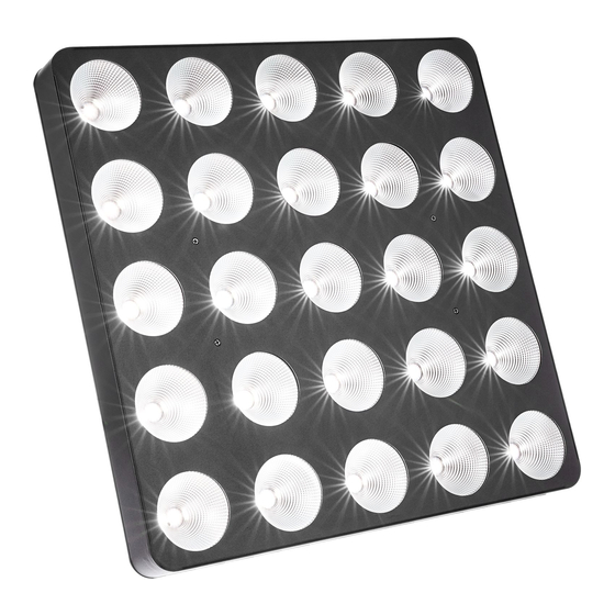
Features Features The LED blinder is particularly suitable for lighting applications in clubs and discotheques, on rock stages, in theatres and musicals. Special features of the device: 25 warm white LEDs (3 W each), arranged in a 5×5 matrix Control via DMX (four different modes) and via buttons and display on the unit 26 preprogrammed automatic shows LED matrix allows the display of letters and numbers Sound control... -
Page 15: Installation
Installation Installation Unpack and carefully check that there is no transportation damage before using the unit. Keep the equipment packaging. To fully protect the device against vibration, dust and moisture during transportation or storage use the original packaging or your own packaging material suitable for transport or storage, respectively. - Page 16 Installation NOTICE! Use of stands When mounting the device onto a stand, ensure that the stand is in a safe and stable position and that the weight of the device does not exceed the maximum permissible load capacity of the stand. NOTICE! Possible data transmission errors For error-free operation make use of dedicated DMX cables and do not use ordi‐...
- Page 17 Installation Always work from a stable platform whenever installing, moving or servicing the unit. Block access under the work area. The safety cable must be routed through this safety eyelet ( Ä Chapter 6 ‘Connections and con‐ trols’ on page 21). Please note that this device must not be connected to a dimmer.
-
Page 18: Starting Up
Starting up Starting up Establish all connections as long as the unit is switched off. Use the shortest possible high- quality cables for all connections. blinder... - Page 19 Starting up Connections in DMX mode Connect the DMX input of the device to the DMX output of a DMX controller or another DMX device. Connect the output of the first DMX device to the input of the second one, and so on to form a daisy chain.
- Page 20 Starting up DMX indicator If the unit is properly connected to a turned on DMX controller, the first position of the display is flashing in DMX mode. If not, the device is not receiving a valid DMX signal. Connections in master/slave When you configure a group of devices in master/slave mode, the first unit will control the mode other units for an automatic, sound-activated, synchronized show.
-
Page 21: Connections And Controls
Connections and controls Connections and controls Rear panel LED Matrix Blinder 5x5 DMX... - Page 22 Connections and controls 1 Connection panel. 2 Locking screws for the mounting bracket. 3 Fan. 4 Buttons and display. 5 Thread holes (M6), fit for connecting elements. 6 Safety eyelet. 7 Bracket for floor placement or hanging. blinder...
- Page 23 Connections and controls Connection panel LED Matrix Blinder 5x5 DMX...
- Page 24 Connections and controls 8 [DMX In] DMX input. 9 [DMX Out] DMX output. 10 [Power In] IEC chassis plug for operating voltage supply with fuse holder. 11 [Power Out] IEC chassis socket for the power supply cable to the next unit. blinder...
- Page 25 Connections and controls Buttons and display LED Matrix Blinder 5x5 DMX...
- Page 26 Connections and controls 12 Display. 13 Button [Down] Decreases the displayed value by one. 14 Button [Up] Increases the displayed value by one. 15 Button [Setup] Selects an option of the respective operating mode, confirms the set value. 16 Button [Mode] Activates the main menu and moves between menu items.
-
Page 27: Operating
Operating Operating 7.1 Starting the device Connect the device to the power supply to start operation. After a few seconds, the display indicates that a reset is in progress. The device is then ready for use. The display shows the operating mode that was selected when the unit was last powered off. - Page 28 Operating Operating mode ‘Preprog‐ Press [Mode] repeatedly until the display shows ‘Pr.xx’ . Now you can select one of the preprog‐ rammed automatic show’ rammed automatic shows. Use [Up] and [Down] to select a value between ‘Pr.01’ and ‘Pr.26’ . To adjust the programme speed, press [Setup].
- Page 29 Operating DMX mode Press [Mode] repeatedly until the display shows ‘dxxx’ . Now you can set the number of the first DMX channel to be used by the device (DMX address). Use [Up] and [Down] to select a value between 1 and 512 (display shows ‘d001’ … ‘d512’ ). Make sure that this number matches the configuration of your DMX controller.
- Page 30 Operating Operating mode ‘Slave’ In the master-slave configuration, you can interconnect four devices of the same type to one large matrix with 10 × 10 LEDs. The effects then use this device combination in common. Press [Mode] repeatedly until the display shows ‘SLAv’ . Press [Setup].
- Page 31 Operating Display of letters and numbers Press [Mode] repeatedly until the display shows ‘ChAr’ . Press [Setup]. With [Up] and [Down] you can now select between the display of letters (display shows ‘Lett’ ) and the display of numbers (display shows ‘nUbe’ ). Press [Setup] again and use [Up] and [Down] to select the letter or the number to be displayed.
-
Page 32: Menu Overview
Operating 7.3 Menu overview blinder... -
Page 33: Functions In 1-Channel Dmx Mode
Operating 7.4 Functions in 1-channel DMX mode Channel Value Function 0…255 Dimmer (0 % to 100 %), for all LEDs together LED Matrix Blinder 5x5 DMX... -
Page 34: Functions In 4-Channel Dmx Mode
Operating 7.5 Functions in 4-channel DMX mode Channel Value Function 0…255 Dimmer (0 % to 100 %), for all LEDs together Operating mode LEDs off 1…11 Preprogrammed automatic show no. 1 12…23 Preprogrammed automatic show no. 2 240…251 Preprogrammed automatic show no. 21 252…255 Sound-controlled show 0…255... -
Page 35: Functions In 26-Channel Dmx Mode
Operating 7.6 Functions in 26-channel DMX mode The figure alongside shows the numbering of the LEDs. Channel Value Function 0…255 Dimmer (0 % to 100 %), for all LEDs together 0…255 Dimmer (0 % to 100 %), for LED no. 1 0…255 Dimmer (0 % to 100 %), for LED no. -
Page 36: Functions In 28-Channel Dmx Mode
Operating 7.7 Functions in 28-channel DMX mode The figure alongside shows the numbering of the LEDs. Kanal Wert Funktion 0…255 Dimmer (0 % to 100 %), for all LEDs together 0…255 Dimmer (0 % to 100 %), for LED no. 1 0…255 Dimmer (0 % to 100 %), for LED no. - Page 37 Operating Kanal Wert Funktion 33…43 Preprogrammed automatic show no. 2 44…54 Preprogrammed automatic show no. 3 242…252 Preprogrammed automatic show no. 21 253…255 Sound-controlled show Selection of the displayed letter (if channel 27 = 10…19) 0…9 Letter ‘A‘ 10…19 Letter ‘B‘ 20…29 Letter ‘C‘...
- Page 38 Operating Kanal Wert Funktion 70…79 Letter ‘H‘ 80…89 Letter ‘I‘ 90…99 Letter ‘J‘ 100…109 Letter ‘K‘ 110…119 Letter ‘L‘ 120…129 Letter ‘M‘ 130…139 Letter ‘N‘ 140…149 Letter ‘O‘ 150…159 Letter ‘P‘ 160…169 Letter ‘Q‘ 170…179 Letter ‘R‘ 180…189 Letter ‘S‘ 190…199 Letter ‘T‘...
- Page 39 Operating Kanal Wert Funktion 200…209 Letter ‘U‘ 210…219 Letter ‘V‘ 220…229 Letter ‘W‘ 230…239 Letter ‘X‘ 240…249 Letter ‘Y‘ 250…255 Letter ‘Z‘ Selection of the displayed number (if channel 27 = 20…29) 0…27 Number ‘0‘ 28…55 Number ‘1‘ 56…83 Number ‘2‘ 84…111 Number ‘3‘...
-
Page 40: Temperature Monitoring
Operating Kanal Wert Funktion 168…195 Number ‘6‘ 196…223 Number ‘7‘ 224…251 Number ‘8‘ 252…255 Number ‘9‘ Speed adjustment (if channel 27 = 30…255) 0…255 Increasing speed 7.8 Temperature monitoring The built-in fan turns on automatically as soon as a certain temperature is reached. If a second temperature limit is exceeded despite the turned on fan, the unit automatically switches off. - Page 41 The temperature-controlled shutoff function is constantly monitored by the device. If a defect is detected, the value ‘rt’ is flashing in the display. In this case, please contact our service centre. Contact details can be found at www.thomann.de. LED Matrix Blinder 5x5 DMX...
-
Page 42: Technical Specifications
Technical specifications Technical specifications Number of DMX channels 1, 4, 26 or 28 channels, according to operating mode Lamp 25 × 3 W LEDs (warm white) Diameter of lenses 9 cm Beam angle approx. 55° Operating supply voltage 100 ... 240 V (AC), 50/60 Hz Power consumption 96 W Fuse... -
Page 43: Plug And Connection Assignments
Plug and connection assignments Plug and connection assignments Introduction This chapter will help you select the right cables and plugs to connect your valuable equip‐ ment so that a perfect light experience is guaranteed. Please take our tips, because especially in ‘Sound & Light’ caution is indicated: Even if a plug fits into a socket, the result of an incorrect connection may be a destroyed DMX controller, a short circuit or ‘just’... -
Page 44: Troubleshooting
Troubleshooting Troubleshooting NOTICE! Possible data transmission errors For error-free operation make use of dedicated DMX cables and do not use ordi‐ nary microphone cables. Never connect the DMX input or output to audio devices such as mixers or ampli‐ fiers. In the following we list a few common problems that may occur during operation. - Page 45 DMX interface circuits. If the procedures recommended above do not succeed, please contact our Service Center. You can find the contact information at www.thomann.de. LED Matrix Blinder 5x5 DMX...
-
Page 46: Cleaning
Cleaning Cleaning Optical lenses Clean the optical lenses, that are accessible from the outside, regularly in order to optimize the light output. The frequency of cleaning depends on the operating environment: wet, smoky or particularly dirty surroundings can cause more accumulation of dirt on the optics of the device. -
Page 47: Protecting The Environment
Protecting the environment Protecting the environment Disposal of the packaging mate‐ rial For the transport and protective packaging, environmentally friendly materials have been chosen that can be supplied to normal recycling. Ensure that plastic bags, packaging, etc. are properly disposed of. Do not just dispose of these materials with your normal household waste, but make sure that they are collected for recycling. - Page 48 Notes blinder...
- Page 49 Notes LED Matrix Blinder 5x5 DMX...
- Page 50 Notes blinder...
- Page 52 Musikhaus Thomann e.K. · Treppendorf 30 · 96138 Burgebrach · Germany · www.thomann.de...
Need help?
Do you have a question about the StairVille LED Matrix Blinder 5x5 DMX and is the answer not in the manual?
Questions and answers