Table of Contents
Advertisement
Quick Links
Advertisement
Table of Contents

Related Manuals for thomann STAIRVILLE LED Matrix Blinder 5x5 MKII


Summary of Contents for thomann STAIRVILLE LED Matrix Blinder 5x5 MKII
- Page 1 LED Matrix Blinder 5×5 MKII blinder user manual...
- Page 2 Thomann GmbH Hans-Thomann-Straße 1 96138 Burgebrach Germany Telephone: +49 (0) 9546 9223-0 Internet: www.thomann.de 27.01.2022, ID: 526644 (V2)
-
Page 3: Table Of Contents
Table of contents Table of contents General information..........................5 1.1 Further information........................... 6 1.2 Notational conventions........................7 1.3 Symbols and signal words....................... 7 Safety instructions..........................10 Features............................... 14 Installation..............................15 Starting up..............................19 Connections and operating elements................... 22 Operating..............................25 7.1 Starting the device........................... - Page 4 Table of contents 7.6 Functions in 26-channel DMX mode..................33 7.7 Functions in 28-channel DMX mode..................34 7.8 Temperature monitoring......................39 Technical specifications........................40 Plug and connection assignments....................43 Troubleshooting............................44 Cleaning............................... 46 Protecting the environment......................47 blinder...
-
Page 5: General Information
Our products and user manuals are subject to a process of continuous development. We there‐ fore reserve the right to make changes without notice. Please refer to the latest version of the user manual which is ready for download under www.thomann.de. LED Matrix Blinder 5×5 MKII... -
Page 6: Further Information
General information 1.1 Further information On our website (www.thomann.de) you will find lots of further information and details on the following points: Download This manual is also available as PDF file for you to download. Use the search function in the electronic version to find the topics of Keyword search interest for you quickly. -
Page 7: Notational Conventions
General information 1.2 Notational conventions This manual uses the following notational conventions: Letterings The letterings for connectors and controls are marked by square brackets and italics. Examples: [VOLUME] control, [Mono] button. Displays Texts and values displayed on the device are marked by quotation marks and italics. Examples: ‘24ch’... - Page 8 General information Signal word Meaning DANGER! This combination of symbol and signal word indicates an immediate dangerous situation that will result in death or serious injury if it is not avoided. WARNING! This combination of symbol and signal word indicates a pos‐ sible dangerous situation that can result in death or serious injury if it is not avoided.
- Page 9 General information Warning signs Type of danger Warning – suspended load. Warning – danger zone. LED Matrix Blinder 5×5 MKII...
-
Page 10: Safety Instructions
Safety instructions Safety instructions Intended use This device is intended for use as an electronic lighting effect by means of LED technology. The device is designed for professional use only and is not suitable for use in households. Use the device only as described in this user manual. - Page 11 Safety instructions Safety DANGER! Danger for children Ensure that plastic bags, packaging, etc. are disposed of properly and are not within reach of babies and young children. Choking hazard! Ensure that children do not detach any small parts (e.g. knobs or the like) from the unit. They could swallow the pieces and choke! Never let children unattended use electrical devices.
- Page 12 Safety instructions WARNING! Risk of epileptic shock Strobe lighting can trigger seizures in photosensitive epilepsy. Sensitive persons should avoid looking at strobe lights. NOTICE! Risk of fire Do not block areas of ventilation. Do not install the device near any direct heat source. Keep the device away from naked flames. NOTICE! Operating conditions This device has been designed for indoor use only.
- Page 13 Safety instructions NOTICE! Fire hazard due to exceedance of the maximum current The device can power other devices of identical construction. The current consumption of all other devices connected in series must not exceed the values indicated in the technical specifications. Otherwise you risk injuries and irreparable damages to the device. Only connect so many identical devices that the maximum current consumption is not exceeded.
-
Page 14: Features
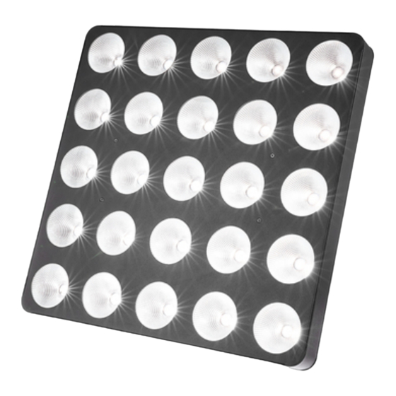
Features Features The LED blinder is particularly suitable for lighting applications in clubs and discotheques, on rock stages, in theatres and musicals. Special features of the device: 25 warm white LEDs (3 W each), arranged in a 5×5 matrix Control via DMX (four different modes) and via buttons and display on the unit 26 preprogrammed automatic shows LED matrix allows the display of letters and numbers Sound control... -
Page 15: Installation
Installation Installation Unpack and check carefully there is no transportation damage before using the unit. Keep the equipment packaging. To fully protect the product against vibration, dust and moisture during transportation or storage use the original packaging or your own packaging material suitable for transport or storage, respectively. - Page 16 Installation NOTICE! Risk of overheating The distance between light output and the illuminated surface must be more than 1.5 m (19.7in). Provide sufficient ventilation. The ambient temperature must always be below 40 °C (104 °F). NOTICE! Use of stands When mounting the device onto a stand, ensure that the stand is in a safe and stable position and that the weight of the device does not exceed the maximum permissible load capacity of the stand.
- Page 17 Installation NOTICE! Possible data transmission errors For error-free operation make use of dedicated DMX cables and do not use ordi‐ nary microphone cables. Never connect the DMX input or output to audio devices such as mixers or ampli‐ fiers. Mounting options You can install the unit in hanging or standing position.
- Page 18 Installation Please note that this device must not be connected to a dimmer. blinder...
-
Page 19: Starting Up
Starting up Starting up Create all connections while the device is off. Use the shortest possible high-quality cables for all connections. Take care when running the cables to prevent tripping hazards. LED Matrix Blinder 5×5 MKII... - Page 20 Starting up Connections in DMX mode Connect the DMX input of the device to the DMX output of a DMX controller or another DMX device. Connect the output of the first DMX device to the input of the second one, and so on to form a daisy chain.
- Page 21 Starting up DMX indicator If the unit is properly connected to a turned on DMX controller, the first position of the display is flashing in DMX mode. If not, the device is not receiving a valid DMX signal. Connections in master/slave When you configure a group of devices in master/slave mode, the first unit will control the mode other units for an automatic, sound-activated, synchronized show.
-
Page 22: Connections And Operating Elements
Connections and operating elements Connections and operating elements ö ö DMX In DMX Out ö ö '& blinder... - Page 23 Connections and operating elements 1 Thread holes (M6), fit for connecting elements 2 Safety cable eyelet 3 Locking screws for the bracket 4 Bracket for floor placement or hanging 5 [DMX OUT] DMX output, designed as XLR panel socket, 3-pin 6 [DMX IN] DMX input, designed as XLR panel plug, 3-pin 7 Fuse holder...
- Page 24 Connections and operating elements 10 Display [Mode] Activates the main menu and toggles between menu items. Closes an opened submenu. [Setup] Selects an option of the respective operating mode, confirms the set value. [Up] Increases the displayed value by one. [Down] Decreases the displayed value by one.
-
Page 25: Operating
Operating Operating 7.1 Starting the device Connect the device to the power supply to start operation. After a few seconds, the display indicates that a reset is in progress. The device is then ready for use. The display shows the operating mode that was selected when the unit was last powered off. - Page 26 Operating Operating mode ‘Preprog‐ Press [Mode] repeatedly until the display shows ‘Pr.xx’ . Now you can select one of the preprog‐ rammed automatic show’ rammed automatic shows. Use [Up] and [Down] to select a value between ‘Pr.01’ and ‘Pr.26’ . To adjust the programme speed, press [Setup].
- Page 27 Operating DMX mode Press [Mode] repeatedly until the display shows ‘dxxx’ . Now you can set the number of the first DMX channel to be used by the device (DMX address). Use [Up] and [Down] to select a value between 1 and 512 (the display shows ‘d001’ … ‘d512’ ). Make sure that this number matches the configuration of your DMX controller.
- Page 28 Operating ‘28ch’ (28 channels) Operating mode ‘Slave’ In the master-slave configuration, you can interconnect four devices of the same type to one large matrix with 10 × 10 LEDs. The effects then use this device combination in common. Press [Mode] repeatedly until the display shows ‘SLAv’ . S.1-1 S.1-2 Press [Setup].
- Page 29 Operating Display of letters and numbers Press [Mode] repeatedly until the display shows ‘ChAr’ . Press [Setup]. With [Up] and [Down] you can now select between the display of letters (display shows ‘Lett’ ) and the display of numbers (display shows ‘nUbe’ ). Press again [Setup] and use [Up] and [Down] to choose the letter or number to be displayed.
-
Page 30: Menu Overview
Operating 7.3 Menu overview blinder... -
Page 31: Functions In 1-Channel Dmx Mode
Operating 7.4 Functions in 1-channel DMX mode Channel Value Function 0…255 Dimmer (0 % to 100 %), for all LEDs together LED Matrix Blinder 5×5 MKII... -
Page 32: Functions In 4-Channel Dmx Mode
Operating 7.5 Functions in 4-channel DMX mode Channel Value Function 0…255 Dimmer (0 % to 100 %), for all LEDs together Operating mode LEDs off 1…11 Preprogrammed automatic show no. 1 12…23 Preprogrammed automatic show no. 2 240…251 Preprogrammed automatic show no. 21 252…255 Sound-controlled show 0…255... -
Page 33: Functions In 26-Channel Dmx Mode
Operating 7.6 Functions in 26-channel DMX mode The figure alongside shows the numbering of the LEDs. Channel Value Function 0…255 Dimmer (0 % to 100 %), for all LEDs together 0…255 Dimmer (0 % to 100 %), for LED no. 1 0…255 Dimmer (0 % to 100 %), for LED no. -
Page 34: Functions In 28-Channel Dmx Mode
Operating 7.7 Functions in 28-channel DMX mode The figure alongside shows the numbering of the LEDs. Channel Value Function 0…255 Dimmer (0 % to 100 %), for all LEDs together 0…255 Dimmer (0 % to 100 %), for LED no. 1 0…255 Dimmer (0 % to 100 %), for LED no. - Page 35 Operating Channel Value Function 40…49 Preprogrammed automatic show no. 2 50…59 Preprogrammed automatic show no. 3 230…239 Preprogrammed automatic show no. 21 240…255 Sound-controlled show Selection of the displayed letter (if channel 27 = 10…19) 0…9 Letter ‘A’ 10…19 Letter ‘B’ 20…29 Letter ‘C’...
- Page 36 Operating Channel Value Function 70…79 Letter ‘H’ 80…89 Letter ‘I’ 90…99 Letter ‘J’ 100…109 Letter ‘K’ 110…119 Letter ‘L’ 120…129 Letter ‘M’ 130…139 Letter ‘N’ 140…149 Letter ‘O’ 150…159 Letter ‘P’ 160…169 Letter ‘Q’ 170…179 Letter ‘R’ 180…189 Letter ‘S’ 190…199 Letter ‘T’...
- Page 37 Operating Channel Value Function 200…209 Letter ‘U’ 210…219 Letter ‘V’ 220…229 Letter ‘W’ 230…239 Letter ‘X’ 240…249 Letter ‘Y’ 250…255 Letter ’Z’ Selection of the displayed number (if channel 27 = 20…29) 0…27 Number ‘0’ 28…55 Number ‘1’ 56…83 Number ‘2’ 84…111 Number ‘3’...
- Page 38 Operating Channel Value Function 168…195 Number ‘6’ 196…223 Number ‘7’ 224…251 Number ‘8’ 252…255 Number ‘9’ Speed adjustment (if channel 27 = 30…255) 0…255 Increasing speed blinder...
-
Page 39: Temperature Monitoring
The temperature-controlled shutoff function is constantly monitored by the device. If a defect is detected, the value ‘rt’ is flashing in the display. In this case, please contact our service centre. Contact details can be found at www.thomann.de. LED Matrix Blinder 5×5 MKII... -
Page 40: Technical Specifications
Technical specifications Technical specifications Light source 25 × LED, each 3 W (warm white) Light source properties Colour temperature 2800 K Colour rendering index 80 Ra Optical properties Beam angle approx. 55° Diameter of lenses 6.3 cm Control DMX, buttons and display on the unit Number of DMX channels 1, 4, 26 or 28 Input connections... - Page 41 Technical specifications Power consumption 110 W Operating supply voltage 100 - 240 V 50 / 60 Hz Fuse 5 mm × 20 mm, 2 A, 250 V, slow-blow Protection class IP20 Mounting options hanging, standing M6 threaded holes, suitable for connecting elements Dimensions (W ×...
- Page 42 Technical specifications Further information Construction Matrix Light source included Illuminant Colour of illuminant DMX controllable blinder...
-
Page 43: Plug And Connection Assignments
Plug and connection assignments Plug and connection assignments Introduction This chapter will help you select the right cables and plugs to connect your valuable equip‐ ment so that a perfect light experience is guaranteed. Please take our tips, because especially in ‘Sound & Light’ caution is indicated: Even if a plug fits into a socket, the result of an incorrect connection may be a destroyed DMX controller, a short circuit or ‘just’... -
Page 44: Troubleshooting
Troubleshooting Troubleshooting NOTICE! Possible data transmission errors For error-free operation make use of dedicated DMX cables and do not use ordi‐ nary microphone cables. Never connect the DMX input or output to audio devices such as mixers or ampli‐ fiers. In the following we list a few common problems that may occur during operation. - Page 45 4. Check whether the DMX cables run near or parallel to high- voltage cables that may cause damage or interference to a DMX interface circuit. If the procedures recommended above do not succeed, please contact our Service Center. You can find the contact information at www.thomann.de. LED Matrix Blinder 5×5 MKII...
-
Page 46: Cleaning
Cleaning Cleaning Optical lenses Clean the optical lenses, that are accessible from the outside, regularly in order to optimize the light output. The frequency of cleaning depends on the operating environment: wet, smoky or particularly dirty surroundings can cause more accumulation of dirt on the optics of the device. -
Page 47: Protecting The Environment
Protecting the environment Protecting the environment Disposal of the packaging mate‐ rial For the transport and protective packaging, environmentally friendly materials have been chosen that can be supplied to normal recycling. Ensure that plastic bags, packaging, etc. are properly disposed of. Do not just dispose of these materials with your normal household waste, but make sure that they are collected for recycling. - Page 48 Notes blinder...
- Page 49 Notes LED Matrix Blinder 5×5 MKII...
- Page 50 Notes blinder...
- Page 52 Musikhaus Thomann · Hans-Thomann-Straße 1 · 96138 Burgebrach · Germany · www.thomann.de...
Need help?
Do you have a question about the STAIRVILLE LED Matrix Blinder 5x5 MKII and is the answer not in the manual?
Questions and answers