Table of Contents
Advertisement
Quick Links
Advertisement
Table of Contents

Related Manuals for LevelOne GSW-2493


Summary of Contents for LevelOne GSW-2493
-
Page 1: User Guide
GSW-2493 4-slot modularized L2 SNMP Switch User Guide... -
Page 3: Table Of Contents
Contents 1. INTRODUCTION ......................1 Features ........................1 Software Features ......................2 Package Contents ......................4 Ethernet Switching Technology ..................5 2. HARDWARE DESCRIPTION ...................6 Physical Dimension ......................6 Front Panel ........................6 LED Indicators ......................6 Rear Panel........................7 Desktop Installation ......................7 Attaching Rubber Feet...................8 Rack-mounted Installation ....................8 Power On........................8 3. - Page 4 About Web-based Management .................60 Preparing for Web Management.................60 Online Help.........................61 System Login ......................61 Port status ........................62 View the Port Information ..................63 Port Statistics......................64 Administrator ......................65 IP Configuration....................65 Switch Setting......................66 Console Port Information..................72 Port Controls......................72 Trunking ......................73 Forwarding and Filtering..................77 VLAN configuration....................80 Spanning Tree .....................88 Port Mirroring.......................90 SNMP Management ....................91...
- Page 5 Diagnosing LED Indicators ..................105 Cabling ....................105 7. TECHNICAL SPECIFICATION ................106...
-
Page 7: Introduction
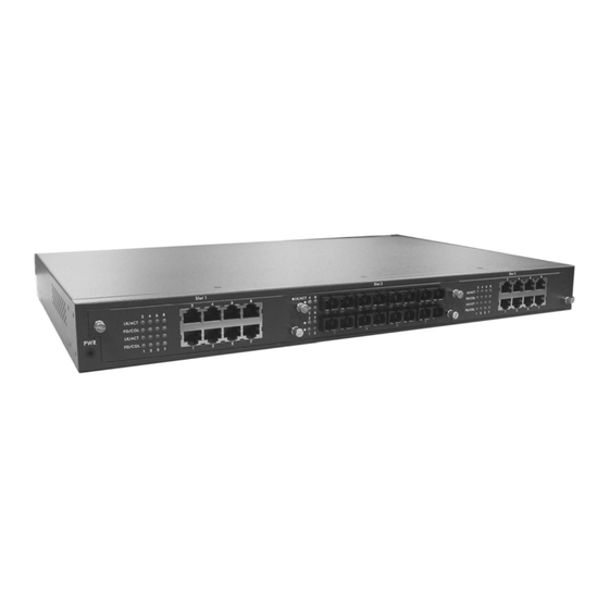
1. Introduction LevelOne GSW-2493, 4-slot intelligent chassis switch, is a modular switch that can be used to build high-performance switched workgroup networks. This switch is a store-and-forward device that offers low latency for high-speed networking. The Switch is targeted at workgroup, department or backbone computing environment. -
Page 8: Software Features
Stack management via one IP address, easy management by Web GUI IGMP support for Multi Media application Support IEEE 802.1p class of service Port security supported Port bandwidth control supported Support IEEE 802.1d Spanning tree protocol Supports GVRP function PortBase VLAN/802.1Q VLAN supported IEEE 802.1X user authentication Support DHCP client Web/ SNMP / Telnet / CLI management... - Page 9 Support IEEE802.3ad with LACP function and provide Port Trunk 7-trunk group of 4 member ports within 26 ports Spanning Tree IEEE802.1d spanning Tree Port based VLAN IEEE802.1Q Tag VLAN VLAN IEEE802.1v Protocol VLAN (IP, IPX,..) Static VLAN groups up to 256, Dynamic VLAN group up to 2048, VLAN ID from 0 to 4094 QOS Policy Supports 8 priority levels ID for two priority queue...
-
Page 10: Package Contents
Authorize Disable DHCP DHCP Client Packet filter Broadcast storm Package Contents Unpack the contents of the and verify them against the checklist GSW-2493 below. GSW-2493 Power Cord Four Rubber Feet RS-232 cable Rack-mounted kit User Guide GSW-2493 Four Rubber Feet... -
Page 11: Ethernet Switching Technology
Power Cord User Manual Figure 1-2. Package Contents Compare the contents of your GSW-2493 package with the standard checklist above. IF any item is missing or damaged, please contact your local dealer for service. Ethernet Switching Technology Ethernet Switching Technology dramatically boosted the total bandwidth of a network,... -
Page 12: Hardware Description
Physical Dimension The GSW-2493 physical dimension is 440mm(W) x 280mm(D) x 44mm(H). Front Panel The Front Panel of the GSW-2493 consists of 3 module slots. One module slot is located in rear-panel of the switch. LED Indicators The LED Indicators gives real-time information of systematic operation status. The LED indicators are located in every module. -
Page 13: Rear Panel
One module slot, 3-pronged power plug, 2 fans, power switching, and one console port is located at the rear Panel of the GSW-2493 as shown in Figure 2-1. The Switch will work with AC power in the range of 100-240V AC, 50-60Hz. -
Page 14: Attaching Rubber Feet
Switch from shock/vibration. Rack-mounted Installation The GSW-2493 come with a rack-mounted kit and can be mounted in an EIA standard size, 19-inch Rack. The Switch can be placed in a wiring closet with other equipment. Perform the following steps to rack mount the switch: Position one bracket to align with the holes on one side of the switch and secure it with the smaller bracket screws. -
Page 15: Network Application
3. Network Application GSW-2493 is designed as a segment switch. That is, with its large address table (8000 MAC address) and high performance, it is ideal for interconnecting networking segments. PC, workstations, and servers can communicate each other by directly connecting with GSW-2493. -
Page 16: Connecting To The Switch
devices to manage); management applications represent the Stack as a single device, and simple point and click management. Stackable technology allows you to increase the resiliency and the versatility of your network edge to accommodate evolution for speed and converged applications. Following figures are example of stacking workgroup application. -
Page 17: Console Management
4. Console Management Login in the Console Interface When the connection between Switch and PC is ready, turn on the PC and run a terminal emulation program or Hyper Terminal and configure its communication parameters to match the following default characteristics of the console port: Baud Rate: 9600 bps Data Bits: 8 Parity: none... -
Page 18: Main Menu
Console login screen Main Menu There are five selections as follow. Status and Counters: Show the status of the switch. Switch Static Configuration: Configure the switch. Protocol Related Configuration: Configure the protocol function. System Reset Configuration: Restart the system or reset switch to default configuration. - Page 19 Main menu line interface Control Key description: The control keys provided in all menus: Tab: Move the vernier to next item. Backspace: Move the vernier to previous item. Enter: Select item. Space: Toggle selected item to next configure or change the value. Esc: to exit the current action mode.
-
Page 20: Function Description
Function Description Status and Counters In Status and Counters, you can view Port status, counters, and configure system parameter. You can press the “Tab” or “Backspace” to choose item, and press “Enter” key to select item. Status and Counters interface Port Status It displays status of port. - Page 21 Negotiation: display the auto negotiation status. FC: display the flow control status is “enable” or “disable”. BP: display backpressure status. Bandwidth In/Out: display bandwidth In/out control status. Priority: display the port priority status. Security: display the port security status. Port status interface Port Counters It displays the current port counter information.
- Page 22 Port counter information interface System Information It displays the system parameter. System Name: the name of device. System Location: where the device is located. System Description: the name of device type. Firmware Version: the switch’s firmware version. Kernel Version: the system kernel software version. Hardware Version: the switch’s Hardware version.
- Page 23 System Information interface...
-
Page 24: Switch Static Configuration
Switch Static Configuration In Switch Static Configuration, it has 8 main functions – Administration, Port, Trunk, Port Mirroring, VLAN, Priority, MAC Address, and Misc Configuration. Under each function, there are more sub-functions. We will describe in following paragraph. Switch Configuration interface Administration Configuration In Administration Configuration, you can configuration system parameter, IP, login username and password. - Page 25 Administration Configuration main interface Device Information You can configure the device information. Select <Edit> action to configure. Name: assign the name for the switch. Description: a short description for the switch. Location: the switch location, ex: Taipei. Contact: the contact person or information. Select <Save>...
- Page 26 Device Information interface IP Configuration You can configure the IP for this switch. The system has the default IP address. You can re-configure or use the default value. 1. Select the <Edit> 2. DHCP Client: disable or enable the DHCP client function. 3.
- Page 27 IP Configuration interface User Name Configuration You can change the console and web management login user name. 1. Select the <Edit> 2. Enter the new user name 3. Select the <Save> User Name Configuration interface...
- Page 28 Password Configuration You can change the console and web management login password. 1. Select the <Edit> 2. Old Password: enter the old password. 3. New Password: enter the new password. 4. Enter Again: reenter the new password for confirmation. 5. Select the <Save> Password Configuration interface Port Configuration You can set up every port status.
- Page 29 mode). BP: enable or disable Back Pressure function (Backpressure for half duplex mode). Bandwidth In/ Out: per port packet transmission rate control. Per level is 100Kbps. It supports individual control method of TX and RX. Priority: set port to high or low priority. 10.
- Page 30 Trunk Configuration interface Port Mirroring Configuration The port mirroring is a method for monitor traffic of switched networks. The specific port can monitor traffic through the mirror ports. The monitored ports in or out traffic will be duplicated into monitoring port. 1.
- Page 31 Port Mirroring interface 3. Analysis port: Set the destination port of mirroring packet. All of the packets of mirroring port will be duplicated and sent to Analysis port. 4. Port State: use “Space” key to mark the port that wanted to be mirrored. 5.
- Page 32 VLAN Configuration You can configure VLAN in VLAN Configuration. There are four functions in VLAN Configuration mode: VLAN Configuration, Create a VLAN Group, Edit/Delete VLAN Group and Group Sorted Node. Follow the below description to configure VLAN. VLAN Configuration Main interface VLAN Configure Before starting to configure VLAN, you must select the VLAN mode in VLAN Configure function.
- Page 33 Acceptable Frame type: It matches that Ingress Filtering Rule 2 on web. Drop untagged frame. Press “Space” key to select drop or forward the untagged frame. 3. Select <Save> to save the configuration. VLAN Configure interface Create VLAN Group Create Port-Based VLAN Select <Edit>.
- Page 34 Create VLAN Group: PortBase interface Create 802.1Q VLAN Enable security VLAN setting: select to enable or disable security VLAN group. When you select to enable security VLAN group, only the members in this VLAN group can access to the switch. The steps of setting security VLAN refer to the following step 2~ 8.
- Page 35 Select <Edit>. VLAN Name: Type a name for the new VLAN, ex: VLAN01. VLAN ID: Type a VID (between 1~4094). The default is 1. There are 256 VLAN groups to provided configure. Protocol VLAN: Press “Space” key to choose protocols type. Member: Press “Space”...
- Page 36 ports from this VLAN group. After edit or delete the VLAN, select <Save> action to save all configures value. NOTE: 1. The VLAN Name and VLAN ID cannot modify. 2. In 802.1Q VLAN mode, the default VLAN can’t be deleting. 3.
- Page 37 Group Sorted Mode interface...
- Page 38 Priority Configuration You can configure port priority level. There are 0~7-priority level can map to high or low queue. Select <Edit>. Press “Space” key to select the priority level mapping to high or low queue. Qos Mode: select the mode to process incoming packets. First comes first service: the switch will process the packet that is coming first.
- Page 39 Priority Configuration interface MAC Address Configuration When you add a static MAC address, it remains in the switch's address table, regardless of whether the device is physically connected to the switch. This saves the switch from having to re-learn a device's MAC address when the disconnected or powered-off device is active on the network again.
- Page 40 Static MAC Address Add the Static MAC Address You can add static MAC address in switch MAC table. Select <Add> <Edit> key to add the static MAC address. MAC Address: Enter the MAC address of the port that should permanently forward traffic, regardless of the device network activity.
- Page 41 Delete static MAC address Select <Delete> key. Choose the MAC address that you want to delete and then press “Enter”. When pressing “Enter” will complete deletion. Filtering MAC Address You can add, delete, and edit filtering MAC address. Filtering MAC Address interface Add the Filtering MAC Address Select <Add>...
- Page 42 Add Filtering MAC Address interface Edit Filtering MAC address Select <Edit> key to modify a static Filtering address. Choose the MAC address that you want to modify and then press “Enter”. Select <Edit> key to modify. Press “ESC” to go back action menu line Select <Save>...
- Page 43 MAC Address Ageing Time: MAC address table refresh time setting. Type the number of seconds that an inactive MAC address remains in the switch’s address table. The valid range is 0, 300~765 seconds. Default is 300 seconds. Broadcast Storm Filter mode: configure the broadcast storm filter mode. The valid threshold values are 5%, 10%, 15%, 20%, 25%, and N/A.
- Page 44 in stacking group. When the stacking group is set up, you can only configure the slave switches through the master switch. Note: Before configuring the stacking function, make sure all stack switches are in the same network. Configure stacking function; you must configure the master switch first. After you have configured the stacking function, use Cat.
-
Page 45: Protocol Related Configuration
Protocol Related Configuration You can configure Spanning Tree Protocol, SNMP, LACP, IGMP/GVRP, and 802.1x in Protocol Relate Configuration section. Protocol Relate Configuration interface Spanning tree is a link management protocol that provides path redundancy while preventing undesirable loops in the network. STP Configuration interface... - Page 46 STP Setup You must enable Spanning Tree function before configure STP function. Select <Edit> Use “Space” key to select the option. Select <Save>. STP Setup interface System Configuration You can configure the STP system parameter after enable the STP function. You can view spanning tree information about the Root Bridge on the left.
- Page 47 STP System Configuration interface Per Port Setting Select <Edit>. Path Cost: specifies the path cost of the port that switch uses to determine which port are the forwarding ports. Priority: This is mean port priority; you can make it more or less likely to become the root port.
- Page 48 Per Port Setting interface SNMP To define management stations as trap managers and to enter SNMP community strings. You can also define a name, location, and contact person for the switch. SNMP Configuration interface...
- Page 49 SNMP System Options Press <Edit>. Name: assign a name for the switch. Contact: Type the name of contact person or organization. Location: Type the location of the switch. Press “ESC” goes back action menu line. Press <Save> to save configure value. SNMP System Options interface Community Strings Add Community Strings...
- Page 50 Add Community Strings interface Edit Community Name Select <Edit> Choose the item that you want to modify and then press “Enter”. Community Name: type the new name. Write Access: Press “Space” key to change the right. Select <Save>. Edit Community Strings interface...
- Page 51 Delete Community Name Select <Delete>. Choose the community name that you want to delete and then press “Enter”. When pressing “Enter” will complete deletion. Trap Managers A trap manager is a management station that receives traps, the system alerts generated by the switch. If no trap manager is defined, no traps will issue. Create a trap manager by entering the IP address of the station and a community string.
- Page 52 Add Trap Manager interface Delete Trap Manager Select <Delete> Choose the trap manager that you want to delete and then press “Enter”. When pressing “Enter” will complete deletion. LACP The Link Aggregation Control Protocol (LACP) provides a standardized means for exchanging information between Partner Systems on a link to allow their Link Aggregation Control instances to reach agreement on the identity of the Link Aggregation Group to which the link belongs, move the link to that Link Aggregation...
- Page 53 LACP Configuration interface Working Ports Setting Select <Edit> Group: Display the trunk group ID. LACP: Press “Space” key to enable or disable LACP (Link Aggregation Control Protocol) support. When LACP enable, the group is LACP static trunk group. When LACP disable, the group is local static trunk group. Working Port Num: The max number of ports can be aggregated at the same time.
- Page 54 LACP Working Ports configuration interface LACP State Activity Select <Edit> Use “Space” key to select the Port State Activity. Active: The port automatically sends LACP protocol packets. Passive: The port does not automatically send LACP protocol packets, and responds only if it receives LACP protocol packets from the opposite device. Select <Save>.
- Page 55 Group Status When you setting trunk group, you can see the relation information in here. LACP Group State interface IGMP/GVRP You can enable or disable the IGMP/GVRP (GARP VLAN Registration Protocol). Select <Edit> Use “Space” key to change the value Select <Save>...
- Page 56 IGMP/GVRP Configuration interface 802.1x 802.1x Configuration interface 802.1x Setup Select <Edit> Use “Space” key to Enable or Disable the 802.1x.
- Page 57 Select <Save> 802.1x Setup interface System Configuration After enabling the IEEE 802.1X function, you can configure the parameters of this function. Select <Edit> Radius Server IP: set the Radius Server IP address. Shared Key: set an encryption key for using during authentication sessions with the specified radius server.
- Page 58 802.1x System Configuration interface Per Port Configuration You can configure 802.1x authentication state for each port. The State provides Disable, Accept, Reject and Authorize. Use “Space” key change the state value. 802.1x Per Port Setting interface...
- Page 59 Misc Configuration Select <Edit> Quiet period: set the period during which the port doesn’t try to acquire a supplicant. TX period: set the period the port wait for retransmit next EAPOL PDU during an authentication session. Supplicant timeout: set the period of time the switch wait for a supplicant response to an EAP request.
-
Page 60: System Reset Configuration
System Reset Configuration System Reset Configuration interface Factory Default Reset switch to default configuration. Press “Y”, switch will load default setting. After finished load default setting, switch will reboot automatically. Factory Default interface... - Page 61 System Reboot Reboot the switch in software reset. TFTP Configuration It provides user to update firmware or restore EEPROM value or upload current EEPROM value. TFTP Update Firmware interface Update Firmware It provides user uses TFTP to update firmware. 1. Start the TFTP server, and copy firmware update version image file to TFTP server. 2.
- Page 62 Update Firmware interface TFTP Restore Configuration You can restore EEPROM value, which saved in TFTP server, from TFTP server. Start the TFTP server. Select <Edit>. TFTP Server IP: type the IP of TFTP server. Restore File Name: type the image file name. Press “ESC”...
- Page 63 TFTP Restore Configuration interface TFTP Backup Configuration You can save current EEPROM value to TFTP server as backup. The backup file can be restore from TFTP server when you need. 1. Start the TFTP server. 2. Select <Edit>. 3. TFTP Server IP: type the IP of TFTP server. 4.
-
Page 64: X-Modem Upgrade
TFTP Backup Configuration interface X-modem Upgrade Before using X-modem upgrade, disconnect terminal and modify baud rate to 57600bps, then connect again. Press “X” key to start upgrading from X-modem. You will see the following screen displays. Select “send file" under Transfer menu from menu bar. Select "browse"... - Page 65 After successfully upgraded the new firmware, please modify baud rate to 9600bps.
-
Page 66: Web-Based Management
5. Web-Based Management This section introduces the configuration and functions of the Web-Based management. If your OS is Windows XP with Service Pack 2, please disable the windows firewall before connecting to UI. About Web-based Management Inside the CPU board of the switch exists an embedded HTML web site residing in flash memory. -
Page 67: Online Help
Password: root Online Help You can click Help button when you have any configuration question during the configuring. System Login Launch the Internet Explorer. Type http:// and the IP address of the switch. Press “Enter”. The login screen appears. Key in the user name and password. The default user name and password is “... -
Page 68: Port Status
GSW-2493 Port status In Port status, you can view every port status that depended on user setting and the negotiation result. Port: display the number of port. The first integer is the module slot number. The second integer is the port number in the module. For example: Port 1-1, it means the first port on the first module slot. -
Page 69: View The Port Information
Back Pressure: Display the Back Pressure status setting. “Config” means the value that user configured. “Actual” means the current value of the port. Bandwidth In/ Out: display the port incoming and outgoing bandwidth. 10. Priority: display the port static priority status is “High” or “Low” or “Disable”. 11. -
Page 70: Port Statistics
Port information interface Port Statistics The following information provides a view of the current port statistic information. Click Clear button to clean all counts. -
Page 71: Administrator
Port Statistics Administrator In Administrator function, it provides the following functions: IP Configuration, Switch Settings, Console Port Information, Port Controls, Trunking, Forwarding and Filtering, VLAN Configuration, Spanning Tree, Port Mirroring, SNMP Management, Security Manager, and 802.1x Configuration. Administrator interface IP Configuration User can configure the IP Settings and DHCP client function, than clicks Apply button. -
Page 72: Switch Setting
IP configuration interface Switch Setting In Switch setting, it has three parts of setting – Basic, Advance, and Misc Config. We will describe the configure detail in following. Basic Switch Settings In Basic Switch Setting, it displays the switch basic information. System Name: the name of switch. - Page 73 Switch basic setting interface Advanced Setting In Advanced setting, it has two sections – MAC Table Address Entry and Priority Queue Service. After the configuration, click button to complete the Apply configuration. Enable MAC address Aging Out: to enable the MAC address age out function. When it is disabling, the following configure item will not function.
- Page 74 port's total bandwidth used by broadcast traffic. When broadcast traffic for a port rises above the threshold you set, broadcast storm control becomes active. The valid threshold value are 5%, 10%, 15%, 20%, 25% and off. Switch Advanced setting interface 802.1p Priority: select the priority queue service type.
- Page 75 Misc Config Collisions Retry Forever: disable is in half duplex. If happen collision will retry 48 times and then drop frame. Enable is in half duplex. If happen collision will retry forever. Hash Algorithm: CRC Hash or Direct Map for MAC address learning algorithm IFG Compensation: Internal Packet Gap time compensation configure.
- Page 76 within a network: 1. Auto mode needs to be enabled when the router’s IP address is smaller than other switches in the subnet. 2. IGMP needs to be enabled when the router’s IP address is not smaller than other switches in the subnet. This Router supports IGMP protocol, but IGMP has to be enabled, and the Router has to be the Querier.
- Page 77 3. The following topology must be set when the IP address of the switch is not the smallest in the subnet. The network will cause a multi-cast storm from the IGMP client report if it is in Auto mode. All switches must be in disable mode when the VOD server is configured for IGMP Querier.
-
Page 78: Console Port Information
Console Port Information Console is a standard UART interface to communicate with Serial Port. User can use windows HyperTerminal program to link the switch. Please refer to Console Management Console login for detail steps. Console port information shows as follow: Bits per seconds: 9600 Data bits: 8 Parity: none... -
Page 79: Trunking
Pressure to confine the ingress rate to meet the specified rate. In: fill in the port effective ingress rate. The valid range is 0 ~ 1000. The unit is 100K. 0: disable rate control. 1 ~ 1000: valid rate value. Out: fill in the port effective egress rate. - Page 80 Group, and enable its transmission and reception functions in an orderly manner. Link aggregation lets you group up to eight consecutive ports into a single dedicated connection. This feature can expand bandwidth to a device on the network. LACP operation requires full-duplex mode, more detail information refers to IEEE 802.3ad.
- Page 81 Trunking—Aggregator Setting interface Aggregator Information When you had setup the LACP aggregator, you will see relation information in here. Trunking – Aggregator Information interface...
- Page 82 Aggregator Information State Activity When you had setup the LACP aggregator, you can configure port state activity. You can mark or un-mark the port. When you mark the port and click button the Apply port state activity will change to Active. Opposite is Passive. Active: The port automatically sends LACP protocol packets.
-
Page 83: Forwarding And Filtering
Forwarding and Filtering IGMP Snooping The switch support IP multicast, you can enable IGMP protocol on web management’s switch setting advanced page, then display the IGMP snooping information in this page, you can view difference multicast group VID and member port in here, IP multicast addresses range from 224.0.0.0 through 239.255.255.255. - Page 84 IGMP Snooping interface Static MAC Address When you add a static MAC address, it remains in the switch's address table, regardless of whether the device is physically connected to the switch. This saves the switch from having to re-learn a device's MAC address when the disconnected or powered-off device is active on the network again.
- Page 85 Static MAC Address interface MAC filtering MAC address filtering allows the switch to drop unwanted traffic. Traffic is filtered based on the destination addresses. In MAC Address box, enter the MAC address that wants to filter. VLAN ID: If tag-based (802.1Q) VLAN are set up on the switch, in the VLAN ID box, type the VID to associate with the MAC address.
-
Page 86: Vlan Configuration
MAC Filtering interface VLAN configuration A Virtual LAN (VLAN) is a logical network grouping that limits the broadcast domain. It allows you to isolate network traffic so only members of the VLAN receive traffic from the same VLAN members. Basically, creating a VLAN from a switch is logically equivalent of reconnecting a group of network devices to another Layer 2 switch. - Page 87 VLAN Configuration interface Port-based VLAN Packets can go among only members of the same VLAN group. Note all unselected ports are treated as belonging to another single VLAN. If the port-based VLAN enabled, the VLAN-tagging is ignored. If an end station sends packets to different VLANs, it has to be either capable of tagging packets it sends with VLAN tags or attached to a VLAN-aware bridge that is capable of classifying and tagging the packet with different VLAN ID based on not only default PVID but also other information about the packet, such as the protocol.
- Page 88 VLAN – PortBase interface Add>> Click to create a new VLAN group. Enter the VLAN name, group ID and select the members of VLAN group. Click Apply...
- Page 89 Add PortBase VLAN interface You will see the VLAN displays. PortBase VLAN group list interface...
- Page 90 If the groups’ list is over one page, you can click Next Page to view other VLAN groups. button to delete unwanted VLAN. Delete Edit button to modify existing VLAN group. 802.1Q VLAN Tagged-based VLAN is an IEEE 802.1Q specification standard. Therefore, it is possible to create a VLAN across devices from different switch venders.
- Page 91 802.1q VLAN interface Basic Click button. Enable GVRP Protocol: check the check box to enable GVRP protocol. Group Name: assign a name for the new VLAN. VLAN ID: fill in a VLAN ID (between 2-4094). The default is 1. Protocol VLAN: choose the protocol type. Default is NONE. From the Available ports box, select ports to add to the switch and click Add>>...
- Page 92 Add 802.1q VLAN interface -1 Click Next . Then you will see the page as follow. Add 802.1q VLAN interface -1 To set the outgoing frames are VLAN-Tagged frames or untagged. Then click...
- Page 93 Apply Tag: outgoing frames with VLAN-Tagged. Untag: outgoing frames without VLAN-Tagged. Port VID: Configure port VID settings Port VLAN ID: enter the port VLAN ID. Ingress Filtering: Ingress filtering lets frames belonging to a specific VLAN to be forwarded if the port belongs to that VLAN. Enable: Forward only packets with VID matching this port's configured VID.
-
Page 94: Spanning Tree
802.1q VLAN – Port VLAN ID interface Spanning Tree The Spanning-Tree Protocol (STP) is a standardized method (IEEE 802.1d) for avoiding loops in switched networks. When STP enabled, to ensure that only one path at a time is active between any two nodes on the network. We are recommended that you enable STP on all switches ensures a single active path on the network. - Page 95 Spanning Tree – System Configuration interface System Configuration You can view spanning tree information about the Root Bridge. You can view spanning tree status about the switch. You can modify STP state. After modification, click Apply button. Priority: assign path priority number. Max Age: the maximum path age Hello Time: the time that controls switch sends out the BPDU packet to check STP current status.
-
Page 96: Port Mirroring
Assign the port priority value. The value range is from 0 to 255. The lowest value has higher priority. Click button. Apply SPT – Per Port Configuration interface Port Mirroring The Port mirroring is a method for monitor traffic in switched networks. Traffic through ports can be monitored by one specific port. -
Page 97: Snmp Management
Analysis Port: It’s mean mirror port can be used to see all monitor port traffic. You can connect mirror port to LAN analyzer or Netxray. Monitor Port: the ports you want to monitor. All monitor port traffic will be copied to mirror port. - Page 98 You can define management stations as trap managers and to enter SNMP community strings. You also can define a name, location, and contact person for the switch. Fill in the system options data, and then click Apply to update the changes. System Options Name: enter a name for the switch.
-
Page 99: Security Manager
MIB-object information. RW: Read write. Enables requests accompanied by this string to display MIB-object information and to set MIB objects. Click Trap Manager A trap manager is a management station that receives traps, the system alerts generated by the switch. If no trap manager is defined, no traps will issue. Create a trap manager by entering the IP address of the station and a community string. - Page 100 802.1X When enabling the IEEE 802.1X function, you can configure the parameters of this function. System Configuration Radius Server IP: set the Radius Server IP address. Server Port: set the UDP destination port for authentication requests to the specified Radius Server. Accounting Port: set the UDP destination port for accounting requests to the specified Radius Server.
- Page 101 Accept: the specified port is required to be held in the Authorized state. Authorized: the specified port is set to the Authorized or Unauthorized state in accordance with the outcome of an authentication exchange between the Supplicant and the authentication server. Disable: The specified port is required to be held in the Authorized state.
-
Page 102: Tftp Update Firmware
Misc Configuration Quiet period: Set the period during which the port doesn’t try to acquire a supplicant. TX period: Set the period the port waits to retransmit next EAPOL PDU during an authentication session. Supplicant timeout: Set the period of time the switch waits for a supplicant response to an EAP request. -
Page 103: Configuration Backup
TFTP Server IP Address: fill in your TFTP server IP. Firmware File Name: the name of firmware image. Click Apply TFTP Update Firmware interface Configuration Backup In Configuration Backup, you can restore the backup configuration into the switch. Also, you can backup the configuration to TFTP server. TFTP Restore Configuration You can restore EEPROM value from TFTP server, but you must put back image in TFTP server, switch will download back flash image. -
Page 104: Tftp Backup Configuration
TFTP Restore Configuration interface TFTP Backup Configuration You can save current EEPROM value from the switch to TFTP server, then go to the TFTP restore configuration page to restore the EEPROM value. TFTP Server IP Address: fill in the TFTP server IP Backup File Name: fill the file name Click Apply... -
Page 105: System Reboot
Subnet mask: 255.255.255.0 The other setting value is back to disable or none. Click button to reset switch to default setting. Default Factory Default interface System Reboot Reboot the Switch in software reset. Click Apply button to reboot the switch. System Reboot interface Panel List Display the switch panel GUI. -
Page 106: Ip Stacking
IP Stacking This function allows switch to stack up to 8 stackable switches as a unit group. When configuring the stacking function, beware the following points. Any port on the switch can be used to stack. Before configuring the stacking function, make sure all stack switches are in the same network. - Page 107 IP Stacking interface Apply Click button to apply the configuration. When the master switch has configured, you will see the following screen. IP Stacking master switch configure finished interface After you have configured the stacking function, use Cat. 5 cable to connect each switch in the stacking group.
- Page 108 communicate and collect the data from the slave switches. Connect to the master switch through the Web. You will see the following screen display. Click any function in the menu bar of the master switch to configure the switch in the stacking group.
- Page 109 Stacking group configuration interface...
-
Page 110: Troubleshooting
6. Troubleshooting This section is intended to help you solve the most common problems on the GSW-2493. Incorrect connections The switch port can auto detect straight or crossover cable when you link switch with other Ethernet device. For the RJ-45 connector should use correct UTP or STP cable, 10/100Mbps port use 2 pairs twisted cable and Gigabit 1000T port use 4 pairs twisted cable. -
Page 111: Diagnosing Led Indicators
at any time. Data path loops will cause broadcast storms that will severely impact your network performance. Diagnosing LED Indicators The Switch can be easily monitored through panel indicators to assist in identifying problems, which describes common problems you may encounter and where you can find possible solutions. -
Page 112: Technical Specification
7. Technical Specification This section provides the specifications of the GSW-2493, and the following table lists these specifications. IEEE802.3 10BASE-T IEEE802.3u 100BASE-TX/100BASE-FX IEEE802.3z Gigabit SX/LX IEE802.3ab Gigabit 1000T Standard IEEE802.3x Flow Control and Back pressure IEEE802.3ad Port trunk with LACP IEEE802.1d Spanning tree protocol... - Page 113 8-port 10/100TX module: RJ-45 8-port 100FX(Multi /Single Mode) module: SC Connector 2-port Gigabit SX/LX module: SC 2-port Gigabit 1000T module: RJ-45 8 port 10/100TX module with RJ-45 connector (MDU-2493TX) 8 port 100Mbps multi mode fiber module with SC Expansion module connector (MDU-2493SXSC) 2 Gigabit copper module with RJ-45 connector (MDU-0140)
- Page 114 -40 ℃ ~70 ℃ , 95% RH Storage temperature FCC Class A, CE Safety UL, cUL, CE/EN60950...
Need help?
Do you have a question about the GSW-2493 and is the answer not in the manual?
Questions and answers