Fisher & Paykel OB24SDPX1 Service Manual
Built in ovens
Hide thumbs
Also See for OB24SDPX1:
- Installation instructions and user manual (57 pages) ,
- Specification sheet (2 pages) ,
- Product dimensions (2 pages)
Table of Contents
Advertisement
Advertisement
Table of Contents

Subscribe to Our Youtube Channel
Related Manuals for Fisher & Paykel OB24SDPX1


Summary of Contents for Fisher & Paykel OB24SDPX1
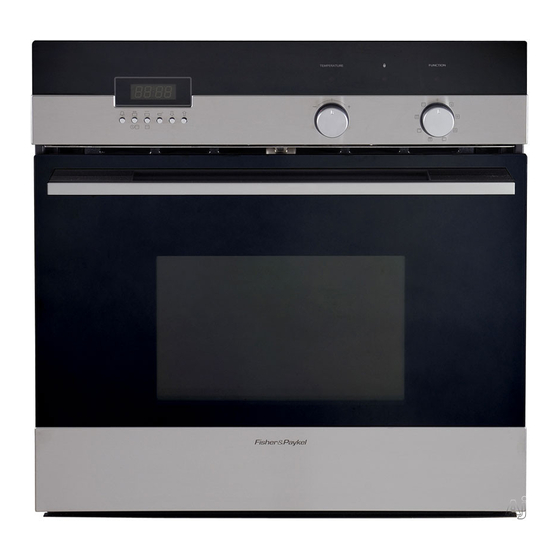
- Page 1 Service Manual Built in Ovens Model: OB24SDPX1 599468...
- Page 2 599468 SEPTEMBER 2007 The model covered by this manual is listed on the front cover. The information detailed in this manual is subject to change without notice. The latest version is indicated by the reprint date and replaces any earlier editions. The front cover picture shows the type of product and may not necessarily be an exact image of the model covered by the manual.
- Page 3 599468 PRODUCTS Brand Fisher & Paykel Model Description Product Code Market OB24SDPX1 Designer, electronic clock, pyrolytic 88487-A Fisher & Paykel Appliances 5900 Skylab Road Huntington Beach CA 92647 Telephone: 888 936 7872 COPYRIGHT © FISHER & PAYKEL LTD 2007 - ALL RIGHTS RESERVED...
-
Page 4: Table Of Contents
599468 CONTENTS SPECIFICATIONS ........................5 Model Descriptions......................5 Electrical Ratings ......................5 SERIAL LABEL ........................6 INSTALLATION ........................7 Cabinetry......................... 7 Securing The Oven ......................7 Air Circulation........................7 OPERATION ..........................8 Setting The Clock......................8 Conditioning The Oven ....................8 Protecting The Enamel Surface ..................8 Condensation And Hot Knobs..................8 Cleaning .......................... -
Page 5: Specifications
= Large font graphics on control panel for visually impaired customers M = Electronic minute timer = Pyrolytic = Electronic (soft touch) controller Colour = Iridium W = White = Brushed stainless Series iteration Electrical Ratings AC 120/240V, 60 Hz Pyrolytic model OB24SDPX1 3095 W, 12.9 A... -
Page 6: Serial Label
599468 SERIAL LABEL • Ser n = serial number, composed of ABBCC-NNNN , where: - A is the last number of the year of manufacture e.g. 7 = 2007. - BB is the week of manufacture e.g. 08 = week 08. - CC –... -
Page 7: Installation
599468 INSTALLATION Cabinetry There is no requirement to install the product in an air-sealed cavity. Securing The Oven Secure the oven into the cabinetry using the screws provided. Air Circulation The space between the bottom of the door and the lower trim is important for the correct air circulation into the oven. -
Page 8: Operation
599468 OPERATION Setting The Clock The oven will not work if the clock has not been set. Refer to the user guide for instructions on how to set the clock. Conditioning The Oven Condition the oven before using it for the first time. Slide in the shelves and grill pan. -
Page 9: Enamel Surfaces
599468 4.5.2 Enamel Surfaces Avoid leaving alkaline or acidic substances (such as lemon juice or vinegar) on the oven surfaces. Do not use cleaning products with a chlorine or acidic base. Replacing The Oven Lamp Never use screwdrivers or other utensils to remove the cover as this could damage the enamel, the cover or the lampholder. -
Page 10: Servicing
599468 SERVICING Pyrolytic Ovens 5.1.1 Electronic Programmer Old Version New Version EL1000 ® The Siebe electronic Programmer is the primary control and monitor device and incorporates the following features: • Oven temperature control. • LED display. • Clock 24 Hour. •... - Page 11 599468 Connected to the mode selector (ST4), the electronic programmer (EL1000) verifies the programme selection by comparing the resistance on the selector with that stored on the programmer’s microchip. When the selected programme has been chosen, a confirmation will be given on the onboard LED display as follows: •...
-
Page 12: Electronic Programmer Testing
599468 Self-Clean (Pyrolytic) Function When the self-clean function is selected on the mode selector, the Electronic Programmer (EL1000) will trigger the following. • Internal cavity temperature confirmed by ST1 probe. • Door closed status confirmed by ST3 microswitch and door lock light is illuminated. •... - Page 13 599468 Full Engineer Test Mode This special mode is for testing single components of the control board. It can only be activated within 10 seconds of the power being supplied and as soon as the cavity temperature has been evaluated. If the cavity temperature is higher than the door locking temperature, the door gets locked and the test mode cannot be entered.
- Page 14 599468 Level 1 Button 1 Oven sensor temperature. Display message "xxx°F" Button 2 Baking mode 0 to 8. Display message "b1” to “B8” corresponding with chosen selector switch position. Button 3 PV +/- position. Display message “Pr xx”. xx is 0 = Neutral, 1 = plus, -1 = minus.
-
Page 15: Wiring Diagram (Old Version Programmer)
599468 5.1.1.3 Wiring Diagram (Old Version Programmer) -
Page 16: Wiring Diagram (New Version Programmer)
599468 5.1.1.4 Wiring Diagram (New Version Programmer) -
Page 17: Door Lock Mechanism
599468 5.1.2 Door Lock Mechanism The door lock mechanism is a bimetal operated door looking system that is used to ensure the oven door is mechanically locked and cannot be opened while the oven is in the self clean mode. 5.1.2.1 Principles of Operation When the oven is switched to the self-clean mode, the main control board on the oven will verify via the door lock microswitch (figure 1), that the door is closed. - Page 18 599468 Microswitch Unlock Lock Bimetallic contact Bimetallic arm. contact arm. Terminals 2 & 3 Terminals 3 & 4. PTC element Oven door latch (unlock) switch. Terminals 33 & 34. PTC element (lock) Figure 2 The door lock mechanism will be locked approximately 30 seconds after the self-clean programme has been selected and will be indicated by the illumination of the “lock”...
-
Page 19: Door Lock Related Issues
599468 5.1.2.2 Door Lock Related Issues The customer may not be initially aware of a failure of the door lock mechanism and the first indication the customer will have is when the control display shows the flashing “DOOR” symbol or an audible sound can be heard. - Page 20 599468 The door lock mechanism should be positioned through the control panel as shown (Figure 5) ensuring that the shim washers are correctly located (Figure 4). Figure 5 The securing screws for the door lock assembly should only be screwed in enough to allow the the lock assembly to still be moved.
-
Page 21: Door Lock Clearance Adjustment
599468 5.1.2.4 Door Lock Clearance Adjustment When the door lock adjustments have been made, the latch should be checked for correct clearance to ensure the door latch will maintain the open position when the door is shut, and will allow the latch to engage at the required depth when locked in the self-clean setting. To ensure correct setting, the door should be pulled slightly away from the cavity until the edge of the latch is level with the door lock block (figure 7). -
Page 22: Door Lock Status Wiring Diagrams
599468 5.1.2.5 Door Lock Status Wiring Diagrams... - Page 23 599468...
- Page 24 599468...
- Page 25 599468...
- Page 26 599468...
-
Page 27: Wiring Diagram
599468 Wiring Diagram... -
Page 28: Fault Codes
599468 FAULT CODES Electronic Oven Fault Codes... - Page 29 599468 MESSAGE VALUE ON CLOCK OF THE DESCRIPTION DISPLAY ERROR E001 Oven cavity temperature probe in short circuit E002 Not used on these models Not used on these models E004 Not used on these models E008 ---- Overheating on the oven cavity E017 16+1 Overheating of oven cavity and temperature probe open circuit...
-
Page 30: Pyrolytic Oven Fault Codes
599468 Pyrolytic Oven Fault Codes... - Page 31 599468...
-
Page 32: Warranty
599468 If F2 is shown in the display, this indicates that the transistor for relay 1 is short circuit or that the supply voltage is less than 150 Volts. The appliance should be turned off for 1 minute and then turned back on. If the F2 indication is still being shown, then the electronic programmer will need to be replaced.
Need help?
Do you have a question about the OB24SDPX1 and is the answer not in the manual?
Questions and answers