Lexmark 7300 series Service Manual
Hide thumbs
Also See for 7300 series:
- User manual (112 pages) ,
- Install manual (2 pages) ,
- Setup sheet (2 pages)
Table of Contents
Advertisement
Quick Links
Advertisement
Table of Contents

Related Manuals for Lexmark 7300 series


Summary of Contents for Lexmark 7300 series
- Page 1 Lexmark™ 7300 Series All-In-One 4418-X6X • Table of contents • Start diagnostics • Safety and notices • Trademarks • Index Lexmark and Lexmark with diamond design are trademarks of Lexmark International, Inc., registered in the United States and/or other countries.
- Page 2 Lexmark and Lexmark with diamond design are trademarks of Lexmark International, Inc., registered in the United States and/or other countries. All other trademarks are the property of their respective owners.
-
Page 3: Table Of Contents
4418-X6X Table of contents Safety information ..........v Preface . - Page 4 4418-X6X Removals ..........4-3 General precautions on removals .
-
Page 5: Safety Information
4418-X6X Safety information • The safety of this product is based on testing and approvals of the original design and specific components. The manufacturer is not responsible for safety in the event of use of unauthorized replacement parts. • The maintenance information for this product has been prepared for use by a professional service person and is not intended to be used by others. - Page 6 4418-X6X Norme di sicurezza • La sicurezza del prodotto si basa sui test e sull'approvazione del progetto originale e dei componenti specifici. Il produttore non è responsabile per la sicurezza in caso di sostituzione non autorizzata delle parti. • Le informazioni riguardanti la manutenzione di questo prodotto sono indirizzate soltanto al personale di assistenza autorizzato.
- Page 7 4418-X6X Pautas de Seguridad • La seguridad de este producto se basa en pruebas y aprobaciones del diseño original y componentes específicos. El fabricante no es responsable de la seguridad en caso de uso de piezas de repuesto no autorizadas. •...
- Page 8 4418-X6X viii Service Manual...
-
Page 9: Preface
4418-X6X Preface This manual contains maintenance procedures for service personnel. It is divided into the following chapters: 1. General information contains a general description of the All-In-One and the maintenance approach used to repair it. Special tools and test equipment are listed, as well as general environmental and safety instructions. - Page 10 4418-X6X Service Manual...
-
Page 11: General Information
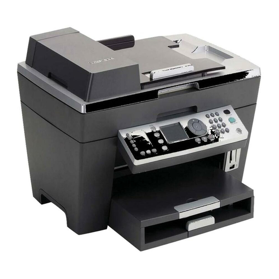
4418-X6X 1. General information The Lexmark™ 7300 Series All-In-One (4418-X6X) is a letter-quality print, fax, copy, and scan machine. It is a standalone color/mono copier and fax. The printhead uses small heater plates and nozzles to control ink flow and the formation of characters on the print media. -
Page 12: Scanner Specifications
4418-X6X Scanner specifications Scanner Type Flatbed, Hybrid CIS/CCD Scan Modes True Color: • 48 bit internal • 24 bit external Gray Mode: • 16 bit internal • 8 bit external Text/Line Art: 1 bit per pixel Scan Method One-pass scanning Scan Area ADF Maximum: •... -
Page 13: Copy Specifications
4418-X6X Copy specifications Copy Modes From the control panel and host: • Color • Black Resolution/Quality The following options are available in Standalone Mode standalone mode. These apply to color copying: Photo–600 X 600 ppi Color Scan 1200 X 1200 dpi print (by interpolation for all papers including glossy paper) Normal–300 X 300 ppi Color Scan 600 X 600 dpi print (by interpolation for all... -
Page 14: Print Speed
4418-X6X Resolution/Quality The following options are available in host- Host-Based Mode based mode. These apply to color/ grayscale copying: Photo–300 X 300 ppi Scan • 1200 X 1200 dpi print • 4800 X 1200 dpi print (for glossy paper) Normal–200 X 200 ppi Scan •... -
Page 15: Using The Control Panel
4418-X6X Using the control panel Press Quick Dial Access any of the five programmed Speed Dial buttons (1—5) numbers. Copy Mode Access the copy menus and make copies. Note: The mode is selected when the button light is on. Scan Mode Access the scan menus and scan documents. - Page 16 4418-X6X Press Redial/Pause • Redial the last number entered when the machine is in Fax mode. • Insert a three-second pause in the number to be dialed. Enter a pause only when you have already begun entering the number. Phone Book Access any of the programmed Speed Dial numbers (1—89) or Group Dial numbers (90—99).
- Page 17 4418-X6X Press • Decrease a number. • Scroll through menus, submenus, or settings on the display. • Cancel a scan, copy, or print job in progress. • Clear a fax number or end a fax transmission, and return to the fax default screen. •...
- Page 18 4418-X6X Press A keypad In Fax mode: number or • Enter fax numbers. symbol • Navigate an automated answering system. • Select letters when creating a Speed Dial list. • Type numbers to enter or edit the date and time shown on the display.
-
Page 19: Maintenance Approach
4418-X6X Maintenance approach The diagnostic information in this manual leads you to the correct field replaceable unit (FRU) or part. Use the error codes, symptom tables, service checks, and diagnostic aids to determine the symptom and repair the failure. After you complete the repair, perform tests as needed to verify the repair. Tools required for service •... -
Page 20: Acronyms
4418-X6X Acronyms Automatic Document Feeder Bill of Material Charge Coupled Device Contact Image Sensor DBCS Double Byte Character Set DPOF Digital Print Order Format Direct Print Service End of Form Electrostatic Discharge Flexible Flat Cable Flat Printhead Cable Field Replaceable Unit HVPS High Voltage Power Supply Kilobyte... -
Page 21: Diagnostic Information
5. The Fax Auto Answer, Copy Mode, Scan Mode, Fax Mode, and Power button lights come on. 6. Lexmark X7300 Series appears on the LCD. 7. The Fax Auto Answer, Copy Mode, and Power lights remain on. 8. Copy Mode appears on the LCD. -
Page 22: Error Codes
4418-X6X Error codes Code Name Description Action 0302 NVRAM R/W An error was detected Replace the system in reading or writing board. NVRAM. 0303 Memory Failure Unable to initialize Replace the system memory board. 0304 Hardware General hardware Replace the system Failure failure (unable to board. - Page 23 4418-X6X Code Name Description Action 1104 Printhead Unsupported order of Install the print Order printheads cartridges in the correct slots. 1105 Auto Alignment Automatic alignment Replace the print Failed has failed. cartridge. 1200 Print Carrier The All-In-One print Unplug the All-In- Stall carrier has stalled.
- Page 24 4418-X6X Code Name Description Action 1207 Paper System A paper system error Clear the paper path. Error control failure was Unplug the detected. All-In-One; wait a few seconds, then plug the All-In-One back in, and turn the power on. If the error remains, replace the system board.
- Page 25 4418-X6X Code Name Description Action 1212 Watchdog Error Indicates printer Unplug the system was reset by All-In-One; wait five Watchdog timer; minutes, then plug Subsystem stall failure. the All-In-One back in, and turn the power on. If the error remains, replace the system board.
- Page 26 4418-X6X Code Name Description Action 1218 Serial Flash Invalid parameters Unplug the Error have been passed to All-In-One; wait a few ReadFlashPage. seconds, then plug the All-In-One back in, and turn the power on. If the error remains, replace the system board.
- Page 27 4418-X6X Code Name Description Action 120A Undefined Microprocessor has Unplug the Error encountered an abort All-In-One; wait a few or undefined seconds, then plug instruction. the All-In-One back in, and turn the power on. If the error remains, replace the system board.
-
Page 28: Post Symptom Table
4418-X6X Code Name Description Action 120F Printhead Installed printhead ID, Replace the print Select print command cartridge. printhead ID, or loaded printhead records do not agree. 121A Loop Timeout Error detected that a Unplug the Error while loop or similar All-In-One;... -
Page 29: Symptom Tables
4418-X6X Symptom Action • The carrier Go to the “Carrier transport service check” on does not page 2-13. move. • The carrier slams the side frame. • The CIS does Go to the “CIS module assembly service check” on not move. page 2-14. -
Page 30: Printer Communication Problems
4418-X6X Control panel problems Symptom Action • Buttons do not work. If the LCD, buttons, or power light fails, check the control panel cable • LCD does not display. connection J6 on the system board, and then run the “Power-On Self Test (POST) sequence”... - Page 31 4418-X6X PictBridge problems Symptom Action The camera does not Check the USB cable connections. If communicate with the printer. connections are okay, go to the “PictBridge service check” on page 2-15. Paper feed problems Symptom Action • Fails to pick up paper Go to the “Paper feed service check”...
- Page 32 4418-X6X Print quality problems Symptom Action • Voids in characters Go to the “Print quality service check” on page 2-19. • Light print • Prints off the page • Fuzzy print • Carrier moves but nothing prints • Printhead dries prematurely •...
-
Page 33: Service Checks
4418-X6X Service checks Carrier transport service check Unit/Problem Action Carrier Transport Check the carrier transport motor connector J10 on the Motor system board. If it is connected, check for approximately 30 V dc on pins 1 and 2 or at the wire connections located on the rear of the carrier transport motor. -
Page 34: Cis Module Assembly Service Check
4418-X6X Unit/Problem Action Carrier Assembly Check the following parts for wear or damage: • Printhead cartridge latch • Latch spring • Carrier • Printhead cables Ensure that all printhead cables are fully seated. If any of these parts are defective, replace the carrier assembly. -
Page 35: Pictbridge Service Check
4418-X6X PictBridge service check Unit/Problem Action PictBridge Check system board connector P1 for approximately Card 4.9 V dc on pin 1. If the voltage is incorrect, replace the system board. Go to “System board removal” on page 4-14. If the voltage is correct but the problem remains, replace PictBridge card assembly with cable. -
Page 36: Paper Feed Service Check
4418-X6X Paper feed service check If the All-In-One does not have paper jam problems, continue with this service check. If the All-In-One has paper jam problems, examine the printer for the following before you begin the service check: • Check the entire paper path for obstructions. •... - Page 37 4418-X6X Unit/Problem Action Paper Pick Check the paper pick motor connector J17 on the Assembly system board. If it is connected, check for approximately 30 V dc on pins 1 and 2 or at the wire connections located on the rear of the paper pick motor.
-
Page 38: Power Service Check
4418-X6X Power service check Unit/Problem Action External Power Plug the external power supply into an outlet, and Supply check for 30 V dc. If the voltage is incorrect, replace the power supply. • Printhead Unplug the All-In-One. Check all connections on the Cables system board, and plug the All-In-One back in. -
Page 39: Print Quality Service Check
4418-X6X Print quality service check Unit/Problem Action Alignment Uneven vertical lines and characters not properly formed (jagged or rough) or not aligned at the left margin can be adjusted by performing the print cartridge alignment. Aligning print cartridges using the control panel 1. - Page 40 4418-X6X Unit/Problem Action Print Cartridge Ensure that the All-In-One contains good print cartridges. Clean the print cartridge nozzles when: • Characters are not printing completely. • White dashes appear in graphics or printed text. • Print is smudged or too dark. •...
- Page 41 4418-X6X Unit/Problem Action Color print Be sure the print cartridge nozzle plate is clean. Clean cartridge cross with a clean, lint-free cloth dampened with water. contamination If cross contamination occurs, check for: • Maintenance station wiper damage • Used tape on the printhead nozzle plate If the wiper is damaged, replace the maintenance station.
-
Page 42: Scan And Copy Quality Service Check
4418-X6X Scan and copy quality service check Unit/Problem Action Scanned images If the scanner glass is dirty, gently wipe it with a clean, have: lint-free cloth dampened with water. • Blank pages Make sure all ink or corrective fluid is dry before placing a document on the scanner glass. -
Page 43: Diagnostic Aids
4418-X6X 3. Diagnostic aids Test page This test prints the test page. To run a complete test page of black and color patterns, be sure the printhead cartridges are in good condition. To enter the test: 1. Turn on the All-In-One. 2. - Page 44 4418-X6X There is a black and color purge pattern used to clear all printhead nozzles. The nozzle test pattern prints all nozzles on a diagonal line. There should be no breaks in the nozzle test pattern. A break in the pattern indicates one or more nozzles are not working.
-
Page 45: Repair Information
4418-X6X 4. Repair information This chapter explains how to make adjustments to the All-In-One and how to remove defective parts. Warning: Read the following before handling electronic parts. Handling ESD-sensitive parts Many electronic products use parts that are known to be sensitive to electrostatic discharge (ESD). -
Page 46: Adjustments
4418-X6X Adjustments The user is directed in the Lexmark Solution Center to perform the printhead alignment adjustments after replacing a print cartridge. Removal procedures The following procedures are arranged according to the name of the All-In-One part discussed. CAUTION: Unplug the power cord before removing any parts. -
Page 47: Removals
4418-X6X Removals General precautions on removals Use caution when disassembling and reassembling components. The close proximity of cables to moving parts makes proper routing a must. When components are removed or replaced, any cables disturbed must be replaced as closely as possible to their original positions. Before removing any component from the machine, be sure you note the cable routing. -
Page 48: Rear Access Cover Removal
4418-X6X Rear access cover removal 1. Remove two screws (A). 2. Remove the rear access cover. Service Manual... -
Page 49: Adf Scanner Lid Assembly Removal
4418-X6X ADF scanner lid assembly removal 1. Remove the rear access cover. 2. Remove ground cable screw (A), and disconnect three cables (B) from the system board. 3. Raise the ADF scanner lid assembly to the upright position. 4. Separate the ADF scanner lid hinges (C) from the scanner module assembly. -
Page 50: Scanner Module Assembly Removal
4418-X6X 5. Lift to remove. Scanner module assembly removal 1. Remove the rear access cover. 2. Disconnect J12 (A) and JP3 (B) from the system board. 3. Lift the scanner module assembly until the risers extend. Service Manual... - Page 51 4418-X6X 4. Disconnect both risers. 5. Lift the scanner module assembly, and remove. Repair information...
-
Page 52: Midframe Cover With Control Panel And Risers Removal
4418-X6X Midframe cover with control panel and risers removal 1. Remove the rear access cover. 2. Remove the ADF scanner lid assembly. 3. Remove the scanner module assembly. 4. Remove the control panel cover. 5. Remove ten screws (A). Service Manual... - Page 53 4418-X6X 6. Lift the midframe cover to disconnect J6 (B) from the system board. 7. Remove the midframe cover with control panel and risers. Repair information...
-
Page 54: Rear Access Door With Sensor Removal
4418-X6X Rear access door with sensor removal 1. Remove the rear access cover. 2. Disconnect JP2 (A) from the system board. 4-10 Service Manual... - Page 55 4418-X6X 3. Use a flat thin-blade screwdriver to separate the rear access door hinge from the base cover. 4. Remove the rear access door with sensor. 4-11 Repair information...
-
Page 56: Fax Card Removal
4418-X6X Fax card removal 1. Remove the rear access cover. 2. Remove the ADF scanner lid assembly. 3. Remove the scanner module assembly. 4. Disconnect J7 (A) from the fax card. 5. Remove four screws (B). 6. Lift and remove the fax card. PictBridge card assembly with cable removal 1. - Page 57 4418-X6X 6. Disconnect P1 (A) from the system board. 4-13 Repair information...
-
Page 58: System Board Removal
4418-X6X 7. Remove two screws (B). 8. Remove the PictBridge card assembly with cable. System board removal 1. Remove the rear access cover. 2. Remove the ADF scanner lid assembly. 3. Remove the scanner module assembly. 4. Remove the midframe cover with control panel and risers. 5. - Page 59 4418-X6X 6. Remove seven screws (A). 7. Lift and remove the system board. 4-15 Repair information...
-
Page 60: Encoder Strip Removal
4418-X6X Encoder strip removal 1. Remove the rear access cover. 2. Remove the ADF scanner lid assembly. 3. Remove the scanner module assembly. 4. Remove the midframe cover with control panel and risers. 5. Disconnect both ends of the encoder strip (A). 6. -
Page 61: Print Engine Removal
4418-X6X Print engine removal 1. Remove the rear access cover. 2. Remove the ADF scanner lid assembly. 3. Remove the scanner module assembly. 4. Remove the midframe cover with control panel and risers. 5. Remove the rear access door with sensor. 6. -
Page 62: Carrier Assembly With Cables, Belt, And Cable Clip Removal
4418-X6X Carrier assembly with cables, belt, and cable clip removal 1. Remove the rear access cover. 2. Remove the ADF scanner lid assembly. 3. Remove the scanner module assembly. 4. Remove the midframe cover with control panel and risers. 5. Remove the print engine. 6. - Page 63 4418-X6X 11. Press cable latch (D), pull the cables through the slot, and remove the carrier assembly. 4-19 Repair information...
-
Page 64: Maintenance Station Removal
4418-X6X Maintenance station removal 1. Remove the rear access cover. 2. Remove the ADF scanner lid assembly. 3. Remove the scanner module assembly. 4. Remove the midframe cover with control panel and risers. 5. Remove the print engine. 6. Press two latches (A). 4-20 Service Manual... - Page 65 4418-X6X 7. Slide the maintenance station forward and remove. 4-21 Repair information...
-
Page 66: Exit Tray Removal
4418-X6X Exit tray removal 1. Remove the rear access cover. 2. Remove the ADF scanner lid assembly. 3. Remove the scanner module assembly. 4. Remove the midframe cover with control panel and risers. 5. Remove the print engine. 6. Use a flat thin-blade screwdriver to separate the exit tray hinge from the base cover. -
Page 67: Printer Base With Cover And Paper Pick Assembly Removal
4418-X6X Printer base with cover and paper pick assembly removal 1. Remove the rear access cover. 2. Remove the ADF scanner lid assembly. 3. Remove the scanner module assembly. 4. Remove the midframe cover with control panel and risers. 5. Remove the print engine. 6. - Page 68 4418-X6X 4-24 Service Manual...
-
Page 69: Locations And Connectors
4418-X6X 5. Locations and connectors System board Connector (total number Connector Description Approximate voltage of pins) Power Supply Pin 1–30 V dc ADF Paper Feed Motor Fax Card Control Panel Ribbon Carrier Ribbon Carrier Ribbon Carrier Ribbon Carrier Pins 1 and 2–30 V dc Transport Motor Paper Feed... - Page 70 4418-X6X Connector (total number Connector Description Approximate voltage of pins) Paper Encoder Pin 1–4.8 V dc Dial Sensor Pin 2–4.8 V dc Pin 3–4.8 V dc Pin 4–4.8 V dc Rear Door Ribbon Media Sensor Scanner Motor Cartridge Access Sensor Service Manual...
- Page 71 4418-X6X Locations and connectors...
-
Page 72: Fax Card
4418-X6X Fax card Connector (total number Connector Description Approximate voltage of pins) Speaker Service Manual... -
Page 73: Pictbridge Card
4418-X6X PictBridge card Connector (total number Connector Description Approximate voltage of pins) PictBridge Pin 1–4.9 V dc Locations and connectors... - Page 74 4418-X6X Service Manual...
-
Page 75: Preventive Maintenance
4418-X6X 6. Preventive maintenance This chapter contains lubrication specifications. Follow these recommendations to prevent problems and maintain optimum performance. Lubrication specifications Lubricate only when parts are replaced or as needed, not on a scheduled basis. Use grease P/N 40X0179 to lubricate the following: •... - Page 76 4418-X6X Service Manual...
-
Page 77: Parts Catalog
4418-X6X 7. Parts catalog How to use this parts catalog The following legend is used in the parts catalog: Asm- Part Units/ Units/ Description Index number mach • Asm-index: Identifies the assembly and the item in the diagram. For example, 2-1 indicates assembly 2 and item number 1. •... -
Page 78: Assembly 1: Covers
4418-X6X Assembly 1: Covers Service Manual... - Page 79 4418-X6X Assembly 1: Covers Asm- Part Units/ Units/ Description Index number mach 40X2652 Cover, midframe with control panel and risers - SBCS 40X2653 Cover, midframe with control panel and risers - DBCS 20W0735 Cover, control panel English 20W0737 Cover, control panel Dutch 20W0739 Cover, control panel French 20W0741...
- Page 80 4418-X6X Assembly 1 (cont.): Covers Service Manual...
- Page 81 4418-X6X Assembly 1 (cont.): Covers Asm- Part Units/ Units/ Description Index number mach 40X2648 Lid, ADF scanner assembly 40X2463 Module, scanner assembly Parts catalog...
-
Page 82: Assembly 2: Engine, Electronics, And Carrier
4418-X6X Assembly 2: Engine, electronics, and carrier Service Manual... -
Page 83: Index
4418-X6X Assembly 2: Engine, electronics, and carrier Asm- Part Units/ Units/ Description Index number mach 40X2646 Card, fax 40X2649 Board, system - SBCS 40X2650 Board, system - DBCS 40X2461 Strip, encoder 40X2645 Engine, print 40X2651 Card, PictBridge assembly with cable 40X2472 Carrier, assembly with cables, belt, and cable clip... - Page 84 4418-X6X Service Manual...
- Page 85 4418-X6X Index symptom tables acronyms 1-10 adjustments error codes ESD-sensitive parts buttons Cancel general information Copy Mode Down Arrow Fax Auto Answer handling ESD-sensitive parts Fax Mode Keypad Lighter/Darker Menu 2-10 Phone Book locations and connectors Power fax card Quality PictBridge card Quick Dial system board...
- Page 86 4418-X6X power problems 2-11 paper pick assembly 2-17 preventive maintenance PictBridge 2-15 print cartridges power 2-18 print quality 2-19 print cartridge 2-20 print quality problems 2-12 print quality 2-19 print speed scan and copy quality 2-22 printer communication problems 2-10 specifications copy scanner...
-
Page 87: Part Number Index
4418-X6X Part number index Description Page 11B6501 Cord, power USA, Peru, Canada, LAD ....11B6502 Cord, power Australia ....... 11B6503 Cord, power UK, Hong Kong . - Page 88 4418-X6X 40X2650 Board, system - DBCS ......40X2651 Card, PictBridge assembly with cable ....40X2652 Cover, midframe with control panel and risers - SBCS .
Need help?
Do you have a question about the 7300 series and is the answer not in the manual?
Questions and answers