Lexmark X46x series Service Manual
Hide thumbs
Also See for X46x series:
- User manual (321 pages) ,
- Service manual (310 pages) ,
- Administrator's manual (79 pages)
Table of Contents
Advertisement
Quick Links
Advertisement
Table of Contents

Related Manuals for Lexmark X46x series


Summary of Contents for Lexmark X46x series
- Page 1 Lexmark™ X46x series 7014-431, 7014-636 7014-637 7014-63w • Table of contents • Start diagnostics • Safety and notices • Trademarks • Index Lexmark and Lexmark with diamond design are trademarks of Lexmark International, Inc., registered in the United States and/or other countries.
- Page 2 Lexmark, Lexmark with diamond design and MarkVision are trademarks of Lexmark International, Inc., registered in the United States and/or other countries. PCL® is a registered trademark of the Hewlett-Packard Company.
-
Page 3: Table Of Contents
7014-xxx Table of contents Table of contents ............iii Notices and safety information . - Page 4 7014-xxx Diagnostics information ............. . . Start .
- Page 5 7014-xxx Flatbed motor service check ........... . . 2-57 Flatbed home position service check .
- Page 6 7014-xxx Hardware Tests ..............3-21 Panel Test .
- Page 7 7014-xxx Print SE Menus ............. 3-41 General .
- Page 8 Lexmark X46x series engine board ..........5-5 Lexmark X46x controller and engine board connector pin values ......5-6 Preventive maintenance .
- Page 9 7014-xxx Assembly 2: Imaging ..............7-4 Assembly 3: Tray assemblies .
- Page 10 7014-xxx Service Manual...
-
Page 11: Notices And Safety Information
7014-xxx Notices and safety information The following laser notice labels may be affixed to this printer. Laser notice The printer is certified in the U.S. to conform to the requirements of DHHS 21 CFR Subchapter J for Class I (1) laser products, and elsewhere is certified as a Class I laser product conforming to the requirements of IEC 60825-1. - Page 12 7014-xxx Avisos sobre el láser Se certifica que, en los EE.UU., esta impresora cumple los requisitos para los productos láser de Clase I (1) establecidos en el subcapítulo J de la norma CFR 21 del DHHS (Departamento de Sanidad y Servicios) y, en los demás países, reúne todas las condiciones expuestas en la norma IEC 60825-1 para productos láser de Clase I (1).
- Page 13 7014-xxx Laserilmoitus Tämä tulostin on sertifioitu Yhdysvalloissa DHHS 21 CFR Subchapter J -standardin mukaiseksi luokan I (1) - lasertuotteeksi ja muualla IEC 60825-1 -standardin mukaiseksi luokan I lasertuotteeksi. Luokan I lasertuotteita ei pidetä haitallisina. Tulostimen sisällä on luokan IIIb (3b) laser, joka on nimellisteholtaan 7 mW:n galliumarsenidilaser ja toimii 655 - 675 nanometrin aallonpituuksilla.
- Page 14 7014-xxx Avís sobre el Làser Segons ha estat certificat als Estats Units, aquesta impressora compleix els requisits de DHHS 21 CFR, apartat J, pels productes làser de classe I (1), i segons ha estat certificat en altres llocs, és un producte làser de classe I que compleix els requisits d’IEC 60825-1.
- Page 15 7014-xxx Notices and safety information...
- Page 16 7014-xxx Service Manual...
-
Page 17: Lithium Warning
7014-xxx Lithium warning CAUTION This product contains a lithium battery. THERE IS A RISK OF EXPLOSION IF THE BATTERY IS REPLACED BY AN INCORRECT TYPE. Discard used batteries according to the battery manufacturer’s instructions and local regulations. Safety information • The safety of this product is based on testing and approvals of the original design and specific components. - Page 18 7014-xxx Sicherheitshinweise • Die Sicherheit dieses Produkts basiert auf Tests und Zulassungen des ursprünglichen Modells und bestimmter Bauteile. Bei Verwendung nicht genehmigter Ersatzteile wird vom Hersteller keine Verantwortung oder Haftung für die Sicherheit übernommen. • Die Wartungsinformationen für dieses Produkt sind ausschließlich für die Verwendung durch einen Wartungsfachmann bestimmt.
- Page 19 7014-xxx Informació de Seguretat • La seguretat d'aquest producte es basa en l'avaluació i aprovació del disseny original i els components específics. El fabricant no es fa responsable de les qüestions de seguretat si s'utilitzen peces de recanvi no autoritzades. •...
-
Page 20: Preface
7014-xxx Preface This manual contains maintenance procedures for service personnel. It is divided into the following chapters: General information contains a general description of the printer and the maintenance approach used to repair it. Special tools and test equipment, as well as general environmental and safety instructions, are discussed. -
Page 21: General Information
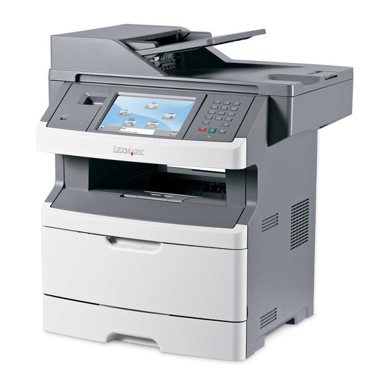
The Lexmark™ X46x series MFPs are users or small workgroups. The X46x MFPs allow users to print, copy, scan, and fax documents. This book contains information on X46x series MFPs. n A4, 25ppm on legal). Maintenance approach The diagnostic information in this manual leads to the correct field replaceable unit (FRU) or part. -
Page 22: Print Engine Specifications
7014-xxx Print engine specifications Memory Item Lexmark X463, X464 Lexmark X466 Standard memory 128MB 128MB Maximum memory 640MB 640MB Optional memory ✔ ✔ 128MB DDR SDRAM unbuffered DIMMS ✔ ✔ 256MB DDR SDRAM unbuffered DIMMS ✔ ✔ 512MB DDR SDRAM unbuffered DIMMS Optional flash memory ✔... -
Page 23: Environment
Width - 20.87 in (530 mm) Depth - 15.5 in (394 mm) w/ input tray set to letter, 16.14 in (410 mm) w/ input tray set to legal. Connectivity and compatibility Item Lexmark X463, X464 LexmarkX466 Data stream emulations ✔... -
Page 24: Media Trays And Supply Capacity
7014-xxx Media trays and supply capacity Item Lexmark X463, X464 Lexmark X466 Available input trays ✔ ✔ Integrated 250-sheet tray ✔ ✔ 50-sheet MP feeder 1-sheet manual feed slot Optional input sources ✔ ✔ 250-sheet drawer ✔ ✔ 550-sheet drawer... -
Page 25: Types Of Print Media
7014-xxx Types of print media Note: Ensure trays are properly loaded. Never mix media types within a tray. Source Sizes Types Weight Input capacity* (sheets) Input tray 1 A4, A5, A6,JIS¹-B5, Plain paper, 60-90 g/m² • 250 paper letter, legal, executive, recycled, labels, •... -
Page 26: Media Guidelines
7014-xxx Media guidelines Paper characteristics The following paper characteristics affect print quality and reliability. Consider these characteristics when evaluating new paper stock. • Weight—The printer can automatically feed paper weights from 60 to 176 g/m (16 to 47 lb bond) grain long. -
Page 27: Selecting Paper
US fed as well as non-recycled paper. However, no blanket statement can be made that all recycled paper will feed well. Lexmark consistently tests its printers with recycled paper (20–100% post-consumer waste) and a variety of test paper from around the world, using chamber tests for different temperature and humidity conditions. - Page 28 7014-xxx Recycled paper, paper of lower weight (<60 g/m [16 lb bond]) and/or lower caliper (<3.8 mils [0.1 mm]), and paper that is cut grain-short for portrait (or short-edge) fed printers may have lower bending resistance than is required for reliable paper feeding. Before using these types of paper for laser (electrophotographic) printing, consult your paper supplier.
-
Page 29: Digital Imaging Specifications
7014-xxx Digital imaging specifications General specifications ADF Scan speed Simplex ADF - Up to 25 ppm Duplex ADF - Up to 35 ppm (page sides) ADF Document handling ADF input capacity - 50 sheets. ADF output capacity - 50 sheets. ADF document width - 4.9’’... -
Page 30: Storage Environments (Unpacked)
Scan Resolutions • Optical - 600 dpi (Local Twain only) • Enhanced (vial Lexmark Scan Center) - 1200 X 1200 dpi, 2400 X 2400 dpi, 4800 X 4800 dpi, 9600 X 9600 dpi, 19200 X 19200 dpi Output resolutions •... -
Page 31: Reduce / Enlarge
7014-xxx Reduce / Enlarge -25% to 400% (Copy only) 1-11 General information... -
Page 32: Fax Specifications
7014-xxx Fax specifications Phone network connectivity Phone networks types supported PSTN or analog PABX (RJ-11) ITU COMPATIBILITY Group 3/ECM 8 x 3.85 pels/mm (200X100dpi) (204x98) Standard Resolution Fine 8 x 7.7 pels/mm (200X200dpi) (204x196) Superfine 11.8 x 11.8 pels/mm (300x300 dpi) (204x391) Ultrafine 15.7 x 15.7 pels/mm (600x600 dpi) (612x587) Coding... -
Page 33: Tools
7014-xxx Tools The removal and adjustment procedures require the following tools and equipment: • Spring hook • Needle nose pliers • Volt-ohmmeter • #1 and #2 Phillips screwdriver • Slotted screwdriver 1-13 General information... -
Page 34: Acronyms
7014-xxx Acronyms Alternating Current Autocompensator Mechanism (or paper feed) Automatic document feeder Analog front end All-In-One Automatic Paper Size ASIC Application Specific Integrated Circuit BLDC Brushless DC Motor Black Only Retract Charge-Couple Device CCFL Cold Cathode Fluorescent Lamp Counter clockwise Command Descriptor Blocks CMYK Cyan yellow magenta black... - Page 35 LASER Light amplification by stimulated emission of radiation Liquid crystal display Liquid Crystal Module Laser Diode Light emitting diode Long edge feed Lexmark Embedded Solution (applications) Laser Scanning Unit Low Voltage LVPS Low voltage power supply Megabyte Motor Driver Control...
- Page 36 7014-xxx Raster image processor Read-only memory Read-only storage Revolutions Per Minute Scanner Control Card SDRAM Synchronous Dynamic Random Access Memory Short edge feed SIMM Single Inline Memory Module Solenoid Start of scan SRAM Static random access memory Toner Add Roll Toner Patch Sensing Tandem Tray Module TVOC...
-
Page 37: Diagnostics Information
The following is an example of the events that occur during the POR sequence when the printer is turned on. Display screen illuminates and the memory test is initiated. The Lexmark splash screen is displayed with a progress bar. The firmware revision is displayed in the lower left of the screen. -
Page 38: Symptom Tables
7014-xxx Symptom tables POST symptom table Symptom Action The main motor, cooling fan, and fuser do not come “Cover interlock switch service check” on page 2-37. POST completes, but the display does not come “Operator panel service check” on page 2-43. -
Page 39: Printer Symptom Table
7014-xxx Printer symptom table Symptom Action Touchscreen displays upside down Replace the display keypad. Fan noisy or fan not working. “Cooling fan service check” on page 2-37. Fuser parts melted. “LVPS/HVPS service check” on page 2-39. Toner not fused to the media. See“Fuser service check”... -
Page 40: Scan / Fax / Copy Symptom Table
7014-xxx Scan / fax / copy symptom table Symptom Action 840.xx scanner error Go to “840.xx service check” on page 2-55. ADF won’t duplex (Duplex ADF only) Go to “ADF Duplex service check” on page 2-62. ADF skew Go to “ADF feed errors service check”... -
Page 41: Overview Of The Operator Panel And Menus
7014-xxx Overview of the operator panel and menus PQRS WXYZ The use of the buttons and the layout of the display panel are described in the following table. Item Description Display View scanning, copying, faxing, and printing options as well as status and error messages. - Page 42 7014-xxx Item Description Home Press to return to the home screen. Start • Press to initiate the current job indicated on the display. • From the home screen, press to start a copy job with the default settings. • If pressed while a job is scanning, the button has no effect. Indicator light Indicates the printer status: •...
-
Page 43: Understanding The Home Screen
7014-xxx Understanding the home screen After the printer is turned on and a short warm-up period occurs, the display shows the following basic screen which is referred to as the home screen. Use the home screen buttons to initiate an action such as copying, faxing, or scanning;... - Page 44 7014-xxx Display item Description Held Jobs Opens a screen containing all the held jobs Lock Device This button appears on the screen when the printer is unlocked and Device Lock- out Personal Identification Number (PIN) has been set. Touching this button opens a PIN entry screen. Entering the correct PIN locks the printer control panel (touch screen and hard buttons).
-
Page 45: Using The Touch-Screen Buttons
7014-xxx Using the touch-screen buttons Note: Depending on your options and administrative setup, your screens and buttons may vary from those shown. Sample touch screen Button Function Home Returns to the home screen Scroll down Opens a drop-down list Left scroll decrease Scrolls to another value in decreasing order Right scroll increase Scrolls to another value in increasing order... -
Page 46: Other Touch-Screen Buttons
7014-xxx Button Function Right arrow Scrolls right Submit Saves a value as the new user default setting Submit Back Navigates back to the previous screen Other touch-screen buttons Button Function Down arrow Moves down to the next screen Up arrow Moves up to the next screen Unselected radio button This is an unselected radio button. - Page 47 7014-xxx Button Function Cancel Jobs Opens the Cancel Jobs screen. The Cancel Jobs screen shows three headings: Print, Fax, and Network. The following items are available under the Print, Fax, and Network headings: • Print job • Copy job • Fax profile •...
-
Page 48: Diagram Of The Printer Menus
7014-xxx Diagram of the printer menus The diagram shows the menu index on the operator panel and the menus and items available under each menu. Not all menus or selections will be available in all situations. These are accessed through the driver. Paper Menu Reports Default Source... -
Page 49: Messages And Error Codes
7014-xxx Messages and error codes User attendance messages The printer control panel displays messages describing the current state of the printer and indicates possible printer problems that must be resolved. This topic provides a list of all printer messages, explains what they mean, and tells how to clear the messages. - Page 50 7014-xxx User status and attendance messages (Continued) User primary message Explanation Held jobs may not be This message is only posted once after the firmware has tried to restore all of the restored (Insufficient jobs on disk, regardless of the number of held jobs that were not restored. There Memory 37) are three versions of this IR, depending upon cause.
- Page 51 7014-xxx User status and attendance messages (Continued) User primary message Explanation Load Manual Printer does not detect media meeting the description <type> and <size> in the <type> <size> single sheet feeder (manual feeder). The following actions can be taken: • Load paper and the job continues. •...
- Page 52 7014-xxx User status and attendance messages (Continued) User primary message Explanation 35 RES Save Off This message displays when the printer lacks sufficient memory to enable Deficient Memory Resource Save. This message usually indicates the user has allocated too much memory for one or more of the printer link buffers;...
- Page 53 7014-xxx User status and attendance messages (Continued) User primary message Explanation 39 Complex Page This message is displayed when a page is too complex to print. The following actions can be taken: • press Select ( ) to clear the message and continue printing. The job may not print correctly.
- Page 54 7014-xxx User status and attendance messages (Continued) User primary message Explanation 56 Serial Port <x> This error displays when data is sent to the printer across an serial port, but the disabled port has been disabled. Once this message displays, reporting of further errors is suppressed until the menus are entered, or the printer is reset.
- Page 55 7014-xxx User status and attendance messages (Continued) User primary message Explanation 1565 Emul Error Load This message is displayed when the DLE's version contained in the firmware card Emul Option will not function with the printer code. The message will automatically clear in 30 seconds, and the DLE will be disabled.
-
Page 56: Cartridge Error Messages
7014-xxx Cartridge error messages Error Description Action Invalid refill Replace the cartridge. Missing or defective cartridge Unsupported print cartridge Paper jam error codes (200-series) Note: The Event log (See “EVENT LOG” on page 3-32) will list any of these errors that have occurred. Repeating jams or jam messages can be caused by any of the following: •... - Page 57 7014-xxx Error Description Action 200.13 The input sensor is covered when the media is not Remove the toner cartridge/PC kit and inspect the expected (media in machine during warm-up) input sensor flag. Replace the flag if necessary. 200.14 Trailing edge cleared manual feed, but did not Remove the toner cartridge/PC kit.
- Page 58 7014-xxx Error Description Action 200.28 First writing line of a page at the developer nip, but Verify that the media is approved. Inspect the wear laser servo cleanup is not complete. Likely pre staged strips in the tray, and replace if they are worn. media or a fast paper feed.
- Page 59 7014-xxx Error Description Action 201.25 Exit sensor never made by leading edge of media Remove the toner cartridge/PC kit and check for when feeding out the media that was detected during obstructions between the input sensor and the fuser. warm-up. if the media continues to stop at the entrance or in the fuser, then replace the fuser.
- Page 60 7014-xxx Error Description Action 231.00 Duplex jam while reversing into the device Open the rear cover and look for obstructions between the rear cover ribs, the fuser exit rollers, and below. The media entering the duplex passes 231.01 Duplex sensor never made by leading edge reversing outside the exit roller while the media exiting the into the duplex.
- Page 61 7014-xxx Error Description Action 251.00 Paper jam near the manual feeder. Inspect the pick roller on the MPF or the rollers on the manual feed. If the MPF pick roller is damaged or worn, then replace the MPF. For a printer with a 251.10 Second pick attempt failed from manual feeder.
-
Page 62: Service Error Codes
7014-xxx Service error codes Service error codes are generally non-recoverable except in an intermittent condition when the printer can be put into POR to temporarily recover from the error condition. Error Description Action 8XX Scanner service errors 840.01 The scanner is disabled and can’t be used. Enter the configuration menu, and re-enable the Scanner scanner module. - Page 63 7014-xxx Error Description Action Rear scan module cable failure or SCC card failure CCD channel failure. Check each channel(mono, R, G, B) for identical values indicating bad cable and/or SCC card. Excessive noise test for the 845.01 dark data indicating some sort of CCD or analog electronics issue on that channel or channels.
- Page 64 7014-xxx Error Description Action HD/Config ID Mismatch A device has a hard drive installed, but its 849.01 Configuration ID indicates that a hard drive shouldn’t be present. Engine software service errors 900.xx RIP software error Turn off MFP for 10 seconds and restart. If error re-occurs, replace controller board.
- Page 65 7014-xxx Error Description Action 929.00 Toner sensor error Remove the toner cartridge, and shake it Try a different toner cartridge, if possible. If the error persists, then replace the toner level sensor. See 929.01 No home window “Toner level sensor removal” on page 4-79.
- Page 66 7014-xxx Error Description Action 954.xx NVRAM chip failure with system part. Replace the controller board. See “Controller board service check” on page 2-35. 955.xx The code ROM or NAND flash failed the Cyclic Redundancy Check or the NAND experienced an uncorrectible multi-bit failure.
-
Page 67: Fax Error Codes
7014-xxx Error Description Action 975.xx Unrecognizable network Call the next level of support. 976.xx Unrecoverable software error in network port 978.xx Bad checksum while programming network port 979.xx Flash parts failed while programing network port Other errors 980.xx Engine experiencing unreliable communication with the Call the next level of support. - Page 68 7014-xxx Fax error log codes (Continued) Error code Description Action Error occurred when sending a frame. • Check line quality. • Adjust ‘Transmit Level’. • Select a lower ‘Max Speed’ value under Fax Send settings. Received EOT unexpectedly from • If error persists disable V34 modulation scheme.
- Page 69 7014-xxx Fax error log codes (Continued) Error code Description Action Timeout occurred after waiting too long • Adjust “Receive Threshold”. to receive a good frame. Tried too many times at selected speed • Adjust ‘Transmit Level’. using V34 modulation scheme. •...
- Page 70 7014-xxx Fax error log codes (Continued) Error code Description Action Failure to transmit training successfully • Adjust “Transmit Level”. at 2400 bps in V27 terminal modulation • Check line quality. scheme. Failed to connect at the minimum • Adjust “Transmit Level”. speed supported by the MFP.
-
Page 71: Service Checks
7014-xxx Service checks Service checks which involve measuring voltages on the LVPS/HVPS (low voltage power supply/ high voltage power supply board) should be performed with the printer positioned on its back side. Note: When making voltage readings, always use frame ground unless another ground is specified. -
Page 72: Engine Board Service Check
7014-xxx Engine board service check Engine board service check Action Engine board POST (Power-On Self Test) assembly Note: The printer should complete POST in approximately 45 seconds. If the printer fails to display lights or activate the drive motor, fuser, or fan, then check the following order: 1. -
Page 73: Card Reader Service Check
7014-xxx Card reader service check Note: The card reader cover will need to be removed, and the op panel keyboard assembly will need to be removed to verify the cable connections. See “Card reader cable removal” on page 4-7. Action Card reader cable Verify that the card reader USB cable is properly connected to the card reader card. -
Page 74: Dead Machine Service Check
7014-xxx Dead machine service check CAUTION: Check the AC line voltage. The voltage should be within the following limits: • 100 V ac (volts alternating current)-127 V ac for the 110 V printer • 200 V ac-240 V ac for the 220 V printer Action Unplug the printer. -
Page 75: Fuser Service Check
7014-xxx Fuser service check When toner is partially fused to the media, it is usually caused by low fuser temperature. The line voltage to the printer must be within the following limits: • 100 V ac-127 V ac for the 110 V model printer •... -
Page 76: Main Motor Service Check
When either support. of these boards is new, • If these voltages are not correct, then see “Lexmark X46x controller and engine it obtains the settings board connector pin values” on page 2-6, or replace the engine board. See “Engine... -
Page 77: Networking Service Check
Have the network administrator verify that the device is using the correct SSID, and wireless security protocols. For more network troubleshooting information, consult the Lexmark Network Setup Guide. - Page 78 7014-xxx Step Questions / actions Try using a different ethernet cable. Problem resolved Go to step 14. Did this remedy the situation? Have the network administrator check the Replace the controller Contact the network network drop for activity. board. Go to “Controller administrator.
-
Page 79: Operator Panel Service Check
7014-xxx Operator panel service check Inspect the operator panel cable for damage. Make sure the cable is plugged in securely. Run POST, and check each light for proper operation. See “Power–On Self Test (POST) sequence” on page 2-1. Touch screen operator panel service check Action Operator panel Display Touchscreen display... -
Page 80: Media Picks But Stops Halfway Through The Printer
7014-xxx Media picks but stops halfway through the printer Action Input/duplex sensors Check the stairway cables to verify they are properly connected to the engine (under print cartridge assembly) board at connectors J500 and J501, and on the controller board at connectors J26 Input sensor (manual) and J27. -
Page 81: Media Skews
7014-xxx Action Engine board Check the stairway cables to verify they are properly connected to the engine board at P/U and manual feed connectors J500 and J501, and on the controller board at connectors J26 and J27. solenoid ASM If they are properly connected verify continuity on both cables. If this fails replace the cables. -
Page 82: Option Card Service Check
7014-xxx Option card service check Option card service check Action Option cards Card Controller board Remove all the option cards from the device. Option card connection Install each card individually. Restart the MFP after each card is installed. cable Remove the card and repeat the previous step with a different card till all cards are Warning: Do not checked. -
Page 83: Print Quality Service Checks
7014-xxx Print quality service checks Note: Ensure the cover closes tightly. A gap in the opening may allow light to expose the photoconductor, resulting in a ‘dirty’ print. Extreme environmental conditions, temperatures, and humidity will affect the print quality. Using print quality test pages To help isolate print quality problems, like streaking, print test pages using the print quality test pages. -
Page 84: Black Page
7014-xxx Black page Note: Incorrect laser exposure or incorrect charging of the photoconductor causes an all black page. Always verify the same results from a different print cartridge assembly and developer before proceeding. Action Toner electrodes (not a Check the three rearward electrodes below the toner cartridge assembly for contamination, FRU) damage, or a short to ground. -
Page 85: Partial Blank Image/White Spots (No Repeating Pattern)
7014-xxx Partial blank image/white spots (no repeating pattern) Action Toner cartridge (not a Remove the toner cartridge assembly, and gently shake the assembly to evenly distribute FRU) the toner. Check to make sure that the laser light path is not blocked. If toner cartridge is low, then try a new one. -
Page 86: Light Print
7014-xxx Light print Action Toner cartridge (not a Make sure the toner cartridge and PC Kit are installed correctly and that the toner cartridge FRU) is not low on toner. If the problem continues, then install a new toner cartridge. Recheck condition before replacing PC Kit, if necessary. -
Page 87: Solving Print Quality Problems
7014-xxx Solving print quality problems Note: Refer to the print defects guide at the end of the manual for repeating defects. Print quality problems Problem Cause / action Light or blurred Light print characters. “Light print” on page 2-50. The toner cartridge may be getting low on toner: •... - Page 88 7014-xxx Print quality problems (Continued) Problem Cause / action Toner smears or rubs • Toner is not being fused to the paper. Replace the fuser. off the page. • Change the media texture setting in the driver. If special media is being used, such as card stock or labels, then be sure to select the correct media type.
- Page 89 7014-xxx Print quality problems (Continued) Problem Cause / action The printer is on and • Make sure the parallel or USB cable is not damaged and is firmly plugged into the indicates ready, but connector on the back of the printer. nothing prints.
-
Page 90: Printhead Service Check
7014-xxx Print quality problems (Continued) Problem Cause / action Unexpected characters • Ensure correct printer driver is being used. print, or characters are • Select hex trace mode to determine what the problem is. missing. • Restore factory defaults. • Make sure the parallel cable or USB cable is firmly plugged in at the back of the printer. Jobs are not printing, •... -
Page 91: Tray 2 Service Check
7014-xxx Tray 2 service check Action Tray 2 Turn the printer off. Separate the printer from Tray 2. Turn the printer on and check the voltages on connector J28 on the engine board. Pins 1, 4: 3.3 V Pin 2: 24 V Pin 6: Ground If the voltages are incorrect, then replace the engine board. - Page 92 7014-xxx Step Questions / actions Replace the ADF cable. POR the machine Go to step 7. Stop. Problem solved. into configuration mode. Go to the disable scanner menu item. See “Disable Scanner” on page 3-36. Touch “Enable ADF/FB -Enabled and press Submit to save the change.
-
Page 93: Black Or Blank Page Copy Service Check
7014-xxx Black or blank page copy service check Step Questions / actions Print a menu page, or a page from the host. “Black page” on Go to step 2. Is the page black? page 2-48 Is the copy an ADF scan? Go to step 4. -
Page 94: Flatbed Home Position Service Check
7014-xxx Flatbed home position service check Step Questions / actions POR the MFP. Does the CCD move and Problem solved. Go to step 2. return to the home position? Perform the home position sensor test. Go Go to step 3. Go to step 5. -
Page 95: Adf Cover Open Service Check
7014-xxx ADF cover open service check Step Questions / actions Is the ADF cover properly closed Go to step 3. Go to step 2. Close the ADF cover. Issue resolved Go to step 3. Does the problem go away? Perform the ADF cover open sensor test. Go Go to step 4 Go to step 8. -
Page 96: Adf Paper Jam Service Check
7014-xxx ADF paper jam service check Note: This service check should be used if the paper feeds and jams in the ADF. If the paper is not feeding into the ADF see “ADF feed errors service check” on page 2-61. Step Questions / actions If the ADF is multi-feeding, check for dirt on... -
Page 97: Adf Feed Errors Service Check
7014-xxx ADF feed errors service check Step Questions / actions If the ADF is multi-feeding, check for Clean them with a lint free Replace the separator pad and dirt on the ADF separator pad and cloth and isopropyl alcohol. ADF pick roll. ADF separator rollers. -
Page 98: Adf Duplex Service Check
7014-xxx ADF Duplex service check Step Questions / actions Perform sensor 1, and sensor 2 Go to step 2. Go to step 3. sensor tests. Go to “Scanner Tests” on page 3-25. Are the sensors working properly? Check the ADF sensor actuators to Go to step 3. -
Page 99: Modem / Fax Card Service Check
7014-xxx Modem / fax card service check Step Questions / actions Is the phone line properly connected to the Go to step 3. Go to step 2. modem card and the wall jack? Properly connect the phone line to the Problem resolved. -
Page 100: Fax Transmission Service Check
7014-xxx Fax transmission service check Note: Before performing this service check, verify that the correct country code for the MFP is selected. This setting must match the country in which the MFP is used to transmit and receive faxes. If the setting is wrong, the modem settings can be changed in the Fax/SE menu. - Page 101 7014-xxx Step Questions / actions Adjust the “Transmit Level” setting in the SE Stop. Problem resolved. Go to your second-level of menu. Press **411 to enter the SE menu, support. See “Escalating a enter Modem settings, and select “Transmit fax issue to second-level Level”.
-
Page 102: Fax Reception Service Check
7014-xxx Fax reception service check Step Questions / actions Is the phone line properly connected to the Go to step 3. Go to step 2. modem card and the wall jack? Properly connect the phone line to the Problem resolved. Go to step 3. - Page 103 7014-xxx Step Questions / actions Go to the Administrator menu. Enter the Fax Go to step 18. Go to step 19. settings - Analog Fax Settings submenu. Verify the remote device number is not in the Banned Fax List user setting. Is the remote device number in the banned fax list? Remove the remote number from the...
-
Page 104: Escalating A Fax Issue To Second-Level Support
7014-xxx Escalating a fax issue to second-level support Before contacting the second-level support, go to the SE menu on the MFP.and generate a Fax error file. This file contains machine settings information and debug information that will help second-level support determine the cause of a failure. -
Page 105: Diagnostic Aids
7014-xxx 3. Diagnostic aids This chapter explains the tests and procedures to identify printer failures and verify repairs have corrected the problem. Accessing service menus There are different test menus that can be accessed during POR to identify problems with the printer. Configuration Menu 1. -
Page 106: Configuration Menu (Config Menu)
7014-xxx Configuration menu (CONFIG MENU) Available menus Maintenance Count Value “Maintenance Count Value (Maint Cnt Value)” on page 3-3. Reset Maintenance Count “Reset Maintenance Counter” on page 3-3. Reset Photoconductor Maintenance “Reset Photoconductor Maintenance Counter (Reset PC Count Cnt)” on page 3-4. -
Page 107: Maintenance Count Value (Maint Cnt Value)
7014-xxx Maintenance Count Value (Maint Cnt Value) This setting enables you to view the current maintenance count value of each maintenance kit. After selecting this item, you can choose a specific kit in order to view its current maintenance count value. To return to the Configuration Menu, press Back. -
Page 108: Reset Photoconductor Maintenance Counter (Reset Pc Cnt)
7014-xxx Reset Photoconductor Maintenance Counter (Reset PC Cnt) This setting resets the photoconductor kit page counter and clears any warnings or photoconductor exhausted messages. This operation should be performed only after a new photoconductor unit has been installed. USB Scan to Local USB Scan to Local enumerates a USB simple device or USB composite device. -
Page 109: Ppds Emulation
7014-xxx To change the value of this setting: 1. Touch Panel Menus from the Configuration Menu. [setting's current value] appears on the touch- screen. 2. Touch to scroll through the setting's other possible values. 3. Touch Back to cancel and return to the Configuration Menu. 4. -
Page 110: Factory Defaults
2. Touch Restore Base to restore all non-critical base printer NVRAM settings. 3. Touch Restore Network to restore all network NVRAM settings. 4. Touch Restore LES to remove all Lexmark Embedded Solution applications When you select either value, the LCD displays Restoring Factory Defaults and then Resetting the Device. The device immediately performs a POR and restores the appropriate settings to their factory default values. -
Page 111: Num Pad Job Assist
7014-xxx Num Pad Job Assist This setting determines if a user can configure and initiate a job using the panels hard buttons. To change this setting: 1. Touch Num Pad Job Assist from the Configuration Menu. [setting's current value] appears on the touch-screen. -
Page 112: Scanner Manual Registration
7014-xxx To adjust the flatbed edge erase setting, perform the following steps: 1. Touch FB Edge Erase from the Configuration Menu. [setting's current value] appears on the touch-screen. 2. Touch to increase the value or to decrease the value. 3. Touch Submit to save the change. 4. -
Page 113: Disable Scanner
7014-xxx Disable Scanner This menu item is used to disable the MFP scanner if it is malfunctioning. The MFP must be powered off and on for the new settings to take effect. To change this setting: 1. Touch Disable Scanner from the Configuration Menu. 2. -
Page 114: Jobs On Disk
7014-xxx Jobs on Disk Jobs On Disk allows you to delete buffered jobs saved on the disk. To delete jobs saved on the disk: 1. Touch Jobs On Disk from the Configuration Menu. 2. Touch to decrease the setting's value; touch to increase the setting's value. - Page 115 7014-xxx The following graphic appears when the formatting process is selected: Formatting Disk DO NOT POWER OFF The panel provides many progress indicators during the two-stage process. • 1/2 indicates that the process is currently in the first stage. • 0% indicates the progress of the current stage of the process.
- Page 116 7014-xxx When the first stage of either process completes, the printer displays either of the following graphics depending on the process selected and then begins the second stage of the process: Encrypting Disk DO NOT POWER OFF Formatting Disk DO NOT POWER OFF The entire process is complete when the progress bar appears completely shaded and the percentage indicator shows 100%.
-
Page 117: Wipe Disk
7014-xxx Wipe Disk This setting provides you with a tool for erasing the contents of a disk. Warning: Wipe Disk removes a disk's data in such a way that it cannot be recovered. To change this setting: 1. Touch Wipe Disk from the Configuration Menu. Note: If an advanced password has been established, you must enter this password in order to change the setting. -
Page 118: Font Sharpening
7014-xxx When the first stage of the process completes, the printer displays the following graphic and then begins the second stage of the process: Wiping Disk DO NOT POWER OFF The entire process is complete when the progress bar appears completely shaded and the percentage indicator shows 100%. -
Page 119: Les Applications
To return to the Ready state more quickly than when operating in Power Saver LES Applications This disables all installed Lexmark Embedded Solution applications. The default is Enabled. To change this setting: 1. Touch LES Applications from the Configuration Menu. -
Page 120: Clear Custom Status
7014-xxx Clear Custom Status No values exist for this operation. Pressing initiates this operation. Touch to select Clear Custom Status from the Configuration Menu. Note: Executing this operation erases any strings that have been defined by the user for the default or alternate custom messages. -
Page 121: Diagnostics Menu
7014-xxx Diagnostics menu Entering Diagnostics menu Turn off the printer. Press and hold 3 and 6. Turn on the printer. Release the buttons after ten seconds. Available tests The tests display on the operator panel in the order shown: Registration “Registration (printer)”... -
Page 122: Registration (Printer)
7014-xxx Registration (printer) Print registration makes sure the printing is properly aligned on the page. REGISTRATION Top Margin Bottom Margin Left Margin Right Margin Quick Test Submit Back The settings available are: Description Value Direction of change Top Margin -25 to +25 A positive change moves the image down the page and increases the top margin. -
Page 123: Quick Test Page
7014-xxx To set print registration: 1. Print the Quick Test page. Touch REGISTRATION from the Diagnostics Menu. Touch to select Quick Test. You may need to scroll to the next page. Retain this page to determine the changes you need to make to the margins settings. The diamonds in the margins should touch the margins of the page. -
Page 124: Print Tests
7014-xxx Print Tests This setting tests the printer’s ability to generate printed output from each of its installed input sources and to test the printer’s current print quality. Input sources The purpose of the diagnostic Print Tests is to verify that the printer can print on media from each of the installed input options. -
Page 125: Hardware Tests
7014-xxx Hardware Tests Select the following Hardware Tests from this menu: • Panel Test • Button Test • DRAM Test • USB HS Test Mode Panel Test This test automatically toggles each pixel of the touchscreen through every contrast level beginning with the darkest and on to the brightest. -
Page 126: Dram Test
7014-xxx DRAM Test The purpose of this test is to check the validity of DRAM memory, both standard and optional. The test writes patterns of data to DRAM to verify that each bit in memory can be set and read correctly. To run the DRAM Test: 1. -
Page 127: Usb Hs Test Mode
7014-xxx USB HS Test Mode 1. Select USB HS Test Mode from HARDWARE TESTS. 2. Press until the appears next to the Port to be tested, and then press 3. Select the desired Test, and then press Port Test Appears on the display Port 0 Test J USB High Speed... -
Page 128: Duplex Tests
7014-xxx Duplex Tests Quick Test (duplex) This test prints a duplex version of the Quick Test that can be used to verify that the correct placement of the top margin on the back side of a duplex page. You can run one duplexed page (Single), or continue printing duplexed pages (Continuous) until Stop is pressed. -
Page 129: Top Margin (Duplex)
7014-xxx Top Margin (duplex) This setting controls the offset between the first scan line on the front of the duplex page and the first scan line on the back of the page. Therefore, be sure to set the top margin in REGISTRATION before setting the duplex top margin. -
Page 130: Duplex Feed 1
7014-xxx 3. Touch Back or press Stop to exit the test. Duplex Feed 1 This test feeds a blank sheet of paper to the duplex paper stop position 1. This test can be run using any of the supported paper sizes. To run the Duplex Feed 1 Test: 1. -
Page 131: Output Bin Tests
7014-xxx 3. Select the sensor to test. Various sources have different combinations of sensors. See the table below: Tray sensor support by source Empty passThru Source (Input tray empty (Input tray paper low (Input tray pass thru sensor) sensor) sensor) Tray 1 Tray 2 Multipurpose tray... -
Page 132: Base Sensor Test
7014-xxx Base Sensor Test This test is used to determine if the sensors located inside the printer are working correctly. To run the Base Sensor Test: 1. Select BASE SENSOR TEST from the DIAGNOSTICS menu. The following sensors are listed: •... -
Page 133: Printer Setup
7014-xxx 3. Once the test is complete, the power indicator turns on solid, and either the message Disk Test/Clean Test Passed or Disk Test/Clean Failed appears. If the message indicates failure, the disk is unusable. PRINTER SETUP PRINTER SETUP Defaults Printed Page Count Permanent Page Count xxxxxxx... -
Page 134: Configuration Id
7014-xxx The model name can only be viewed and cannot be changed. Configuration ID The two configuration IDs are used to communicate information about certain areas of the printer that cannot be determined using hardware sensors. The configuration IDs are originally set at the factory when the printer is manufactured, however, the servicer may need to reset Configuration ID 1 or Configuration ID 2 whenever you replace the system board. -
Page 135: Ep Setup
7014-xxx EP SETUP EP SETUP EP Defaults Fuser Temp Normal Fuser Page Count Warm Up Time Transfer Medium Print Contrast Medium Submit Back The triangles pointing up or down indicate whether there are additional menus. Touch the up or down arrows to display these additional menus. -
Page 136: Transfer
7014-xxx Touch Back to return to Diagnostics Menu. Transfer The transfer can be adjusted to Low, Medium, or High. The default setting is Medium. Touch Back to return to Diagnostics Menu. Print Contrast The print contrast setting controls the developer voltage offset. The print contrast can be adjusted to Low, Medium, or High. -
Page 137: Print Log
Page counts for most errors • Additional debug information in some cases The printed event log can be faxed to Lexmark or your next level of support for verification or diagnosis. To print the event log: Touch to select Print Log from EVENT LOG. -
Page 138: Scanner Tests
7014-xxx Scanner Tests ASIC Test A pattern appears and ASIC Test Passed displays. If xxxxxx displays, the test was unsuccessful. Press Stop to return to the SCANNER TESTS menu. Feed Test To run the Scanner Feed test: 1. Touch to select Feed Test from the SCANNER TESTS menu. 2. - Page 139 7014-xxx To test the paper present sensor, push back on the actuator (A). If the sensor is functioning, the 0 next to the P on the display will change to 1. To test the flatbed cover closed sensor, lift the flatbed cover. The 0 next to the F will change to 1. Also check the actuator (B) to ensure it is functiong properly.
- Page 140 7014-xxx To test scanner sensor 1 press on the tab (C). The 0 next to the 1 will change to 1 if the sensor is working properly. To test scanner sensor 2 press on the tab (D). The 0 next to the 2 will change to 1 if the sensor is working properly.
-
Page 141: Exit Diagnostics
7014-xxx Exit Diagnostics Selecting EXIT DIAGNOSTICS exits the Diagnostics menu, and Resetting the Printer displays. The printer performs a POR, and the printer returns to normal mode. 3-37 Diagnostic aids... -
Page 142: Printhead Assembly Electronic Adjustment
7014-xxx Printhead assembly electronic adjustment Note: Before aligning the printhead electronically, first align the printhead mechanically, if needed. See “Printhead assembly mechanical adjustment” on page 3-39. Enter the Diagnostics menu. See “Entering Diagnostics menu” on page 3-17. Touch Registration to enter the Registration menu. Touch Quick test to print the Quick test page. -
Page 143: Printhead Assembly Mechanical Adjustment
7014-xxx Print the Quick Test page again and check that the darkest line in the center graph is equal to zero. If it is, then check to see if the left, top, and bottom margins are detected. If it is not, then repeat step 5. Note: The alignment of the left margin positions the black plane to the right or left. - Page 144 7014-xxx If the grid lines of the right flap align below the corresponding lines on the left flap, then adjust the printhead clockwise relative to the printer, and recheck. (See the left side of the figure below.) If the grid lines of the left flap align below the corresponding lines of the right side, then adjust the printhead counterclockwise.
-
Page 145: Se Menu
7014-xxx SE Menu Note: This is not the Fax SE menu. To enter the Fax SE menu, press **411 from the Ready screen. Note: This menu should be used as directed by second-level support. Print SE Menus General Copyright - Displays copyright information. Optra Forms mode - On or off Code Revision Info Network Code Level - Displays network code level... -
Page 146: Paper Jams
Have any exposed adhesive when the flap is in the sealed position • Use only recommended media. Refer to the Card Stock & Label Guide available on the Lexmark Web site at www.lexmark.com for more information about which media provides optimum results for the current printing environment. -
Page 147: Understanding Jam Numbers And Locations
7014-xxx Understanding jam numbers and locations The following illustration shows the areas of the MFP where jams occur. When paper jams occur, follow the instructions in this section. Jam area Description number Opened front door Paper output bin Front door Multi purpose feeder Tray 1 Tray 2... -
Page 148: Jam Messages And Their Locations
7014-xxx Jam messages and their locations 200 and 201 paper jams CAUTION: Hot surface. The inside of the printer may be hot. To reduce the risk of injury from a hot component, allow the surface to cool before touching it. Pull the tray completely out. - Page 149 7014-xxx If the paper is not visible, open the front door and remove the photoconductor kit and toner cartridge. Remove the jam. If the paper is still not visible, open the rear door. Remove the jam. 3-45 Diagnostic aids...
-
Page 150: 202 Paper Jam
7014-xxx Close the rear door. Reinsert the photoconductor kit and toner cartridge. Close the front door. Touch Continue. 202 paper jam Touch Status/Supplies to identify the location of the jam. If the paper is exiting the MFP into the exit bin, pull the paper out and touch Continue. - Page 151 7014-xxx Remove the jam. Close the rear door. Close the front door. Touch Continue. 3-47 Diagnostic aids...
-
Page 152: 233 Paper Jam
7014-xxx 233 paper jam Remove the tray from the printer. Locate the duplex release lever and pull it down to release the paper. Insert the tray. Touch Continue. If this does not clear the jam, perform the steps found in 231 paper jam. See “231 paper jam”... -
Page 153: 240 - 249 Paper Jams
7014-xxx 235 paper jam Gently pull the jammed media from the fuser. Touch Continue. 240 - 249 paper jams Touch Supply/Status to identify the jam location. Remove the standard tray. Remove any jammed paper. Reinsert the tray, and touch Continue. If the jam message remains, remove the optional tray. - Page 154 7014-xxx Remove any jammed paper. Reinsert the option tray, and touch Continue. 250 paper jam Touch Supplies/Status to find the jam location. Remove the media from the multipurpose feeder. Remove the jammed media from the multipurpose feeder. Flex and fan the media. Reload the media into the multi purpose feeder.
-
Page 155: Paper Jam
7014-xxx 251 paper jam If the media is visible from the front of the MFP, gently pull the media out of the multipurpose feeder. If the media is not visible, perform the following steps to clear the jam: Open the front door, and remove the photoconductor kit and toner cartridge. Lift the flap at the front of the MFP, and remove any jams. -
Page 156: 290-294 Paper Jams
7014-xxx Close the front door. Touch Continue. 290-294 paper jams Clearing jams under the ADF cover Remove all original documents from the ADF input tray. Open the ADF cover. Unlock the ADF separator roll. 3-52 Service Manual... - Page 157 7014-xxx Remove the ADF separator roll. Remove the jammed media. Reinstall the ADF separator roll. 3-53 Diagnostic aids...
- Page 158 7014-xxx Lock the ADF separator roll. Close the ADF top cover. Clearing ADF jams under the flatbed cover. Lift the flatbed cover, and remove the jammed media from the ADF. Touch Continue. 3-54 Service Manual...
- Page 159 7014-xxx Clearing jams in the duplex ADF Remove the ADF input tray. Pull out the jammed media by pulling on the bottom sheet. Reinstall the ADF input tray. Touch Continue. 3-55 Diagnostic aids...
- Page 160 7014-xxx 3-56 Service Manual...
-
Page 161: Repair Information
7014-xxx 4. Repair information Warning: Read the following before handling electronic parts. Handling ESD-sensitive parts Many electronic products use parts that are known to be sensitive to electrostatic discharge (ESD). To prevent damage to ESD-sensitive parts, follow the instructions below in addition to all the usual precautions, such as turning off power before removing logic cards: •... -
Page 162: Removal Procedures
7014-xxx Removal procedures • Remove the toner cartridge and media tray before removing other printer parts. The toner cartridge should be protected from light while out of the printer. • We recommend disconnecting all external cables from the printer to prevent damage during service. •... -
Page 163: Acm Pick Tire Roller Removal
7014-xxx ACM pick tire roller removal Place the printer on its side. Note: Be careful to not mar the finish of the printer. Open the duplex jam door just far enough to pull out the ACM pick tires. Warning: Open the duplex door only far enough to remove the ACM pick tires. If the door is opened too far, then it can become disengaged and interfere with the paper tray. - Page 164 7014-xxx Remove the ACM pick tire roller (A). • If the left hub is gray, then disconnect the old right and left tire/hub assemblies from the ACM, and replace with the new right and left tire/hub assemblies. • If the left hub is black, then remove the old right and left tires from the ACM hubs, and replace with the new tires.
-
Page 165: Card Reader Removal
7014-xxx Card reader removal Remove the scanner front cover. See “Scanner front cover removal” on page 3-31. Remove the operator panel keypad assembly. See “Operator panel keypad removal” on page 4-62 Release the tabs on the rear of the operator panel display and tilt it upright. Remove the two screws (A) securing the card reader housing to the tub assembly. -
Page 166: Upper And Lower Card Reader Cover Removal
7014-xxx Upper and lower card reader cover removal Remove the scanner front cover. See “Scanner front cover removal” on page 3-31. Remove the card reader. See “Card reader removal” on page 4-5. Remove the four screws (A) fastening the upper and lower card reader covers. -
Page 167: Card Reader Cable Removal
7014-xxx Card reader cable removal Remove the scanner front cover. See “Scanner front cover removal” on page 3-31. Remove the operator panel keypad assembly. See “Operator panel keypad removal” on page 4-62 Release the tabs on the rear of the operator panel display and tilt it upright. Disconnect the card reader cable (A) from the J2 USB port on the controller board. -
Page 168: Controller Board Removal
7014-xxx Controller board removal CAUTION This product contains a lithium battery. THERE IS A RISK OF EXPLOSION IF THE BATTERY IS REPLACED BY AN INCORRECT TYPE. Discard used batteries according to the battery manufacturer’s instructions and local regulations. Warning: • Always touch a ground before touching the board. - Page 169 7014-xxx Using a flatblade screwdriver, depress the kickstand release tab (B). While depressing the tab, lift the scanner assembly until it is fully vertical. Carefully tilt the ADF down as shown. Warning: To avoid damage to the rear frame assemblies, hold the ADF while raising the flatbed to the upright position, then lower the ADF, slowly a shown above.
- Page 170 7014-xxx Remove the seven screws (C) securing the controller board to the controller board cage. Lift the controller board, and remove. Note: When installing the controller board, place the USB port screw first, and then place the controller board screws. 4-10...
-
Page 171: Controller Board Shield
7014-xxx Controller board shield Remove the two screws (A) securing the controller shield bracket to the controller board cage. 4-11 Repair information... - Page 172 7014-xxx Remove the three screws (B) securing the top of the controller shield. 4-12...
- Page 173 7014-xxx Loosen the three screws (C) on each side of the controller board cage. Remove the controller board shield. 4-13 Repair information...
-
Page 174: Controller Board Cage
7014-xxx Controller board cage Remove the controller board. See Go to “Controller board removal” on page 4-8. Remove the five screws (A) which secure the controller board cage to the tub assembly. Tilt the front of the cage up and remove it from the MFP. Controller board fan Remove the operator panel display. -
Page 175: Engine Board Removal
7014-xxx Engine board removal CAUTION This product contains a lithium battery. THERE IS A RISK OF EXPLOSION IF THE BATTERY IS REPLACED BY AN INCORRECT TYPE. Discard used batteries according to the battery manufacturer’s instructions and local regulations. Remove the right side cover. See Go to “Right side cover removal”... -
Page 176: Cover Open Sensor
7014-xxx Cover open sensor Remove the right side cover. Go to “Right side cover removal” on page 4-77. Disconnect the cable from connector J11 on the controller board. Use a #1 Phillips screwdriver to remove the screw (A) holding the sensor. Remove the cover open sensor. -
Page 177: Door Mount Removal
7014-xxx Door mount removal Open the front cover. Remove the lower front cover. See “Lower front cover removal” on page 4-35. Remove the left side cover. See “Left side cover removal” on page 4-33. Remove the right side cover. See “Right side cover removal”... - Page 178 7014-xxx Disconnect the fuser link (B). Remove the three screws (C) from the left side of the printer. Remove the door mounts. 4-18...
-
Page 179: Duplex Removal
7014-xxx Duplex removal Remove the right side cover. See “Right side cover removal” on page 4-77. Remove the LVPS/HVPS. See “LVPS/HVPS removal” on page 4-37. Remove the three screws (A) from the shield. Remove the four screws (B) from the duplex. 4-19 Repair information... - Page 180 7014-xxx Lift the duplex slightly, push to the left, and tilt to clear the right side of the printer. Remove the duplex. 4-20...
-
Page 181: Duplex/Main Motor Gear Drive Interface Removal
7014-xxx Duplex/main motor gear drive interface removal Remove the LVPS/HVPS. See “LVPS/HVPS removal” on page 4-37. Remove the duplex. See “Duplex removal” on page 4-19. Remove the main motor gear drive. See “Main motor gear drive removal” on page 4-40. Remove the e-clip (A) from the gear. - Page 182 7014-xxx Remove the screw (D) from the gear (E). Remove the plastic bushing (F). 4-22...
- Page 183 7014-xxx Use a screwdriver to pop the retainer clip (G) loose from the gear. Remove the gear (H). 4-23 Repair information...
-
Page 184: Fan Removal
7014-xxx Fan removal Remove the right side cover. See “Right side cover removal” on page 4-77. Disconnect the cable (A) from the engine board, and remove the two screws (B) holding the fan to the right side frame. Remove the fan. 4-24... -
Page 185: Front Access Door Removal
7014-xxx Front access door removal Remove the front door access cover. See “Front door access cover removal” on page 4-34. Remove the left side cover. See “Left side cover removal” on page 4-33. Remove the upper front guide assembly. See “Upper front guide assembly removal”... - Page 186 7014-xxx Disconnect the MPF from the lower front cover. Disconnect the fuser link (A) from the front access door. 4-26...
- Page 187 7014-xxx Disconnect the front access door from its hinges, and remove. Installation note: Install a new front access door at its hinges. Connect the fuser link. Remove the two screws (D). Slide the latch to the left to free it, and then rest it on the door. Keep the spring in place. Finish tightening the screws (F), and reinstall the remaining parts.
-
Page 188: Fuser Removal
7014-xxx Fuser removal Remove the rear exit guide. See “Rear exit guide assembly with sensor and reversing solenoid removal” on page 4-75. Remove the two screws (A). Partially pull the fuser forward for better access. 4-28... - Page 189 7014-xxx Push in on the cable connector cover (B), and remove. Disconnect the AC cable (C). Disconnect the thermistor cable (D). 4-29 Repair information...
- Page 190 7014-xxx Disconnect the exit sensor cable (E) from the engine board. Remove the fuser. Note: • Be careful to not damage the gears during the fuser installation. • Be sure to reinstall the AC cable during the fuser installation. 4-30...
-
Page 191: Scanner Front Cover Removal
7014-xxx Scanner front cover removal Use a flatblade screwdriver to pry the scanner front cover away from the side cover. Be careful to avoid marring the finish. 4-31 Repair information... - Page 192 7014-xxx Carefully pull the scanner front cover away from the tub assembly. 4-32...
-
Page 193: Left Side Cover Removal
7014-xxx Left side cover removal Note: • Leave the front door closed when removing the left side cover. • Make sure that the fuser cables are out of the way when removing the left side cover. Remove the scanner front cover. See “Scanner front cover removal”... -
Page 194: Front Door Access Cover Removal
7014-xxx Depress the two tabs (C) on the underside of the MFP. Lift the left cover up and pull the bottom of the cover away from the MFP. Front door access cover removal Remove bumper. See “Nameplate cover removal” on page 4-61. -
Page 195: Lower Front Cover Removal
7014-xxx Lower front cover removal Open the lower front cover. Disconnect the MPF pins (A) from the right and left sides of the lower front cover. Flex the lower front cover, and disconnect it first from its right hinge and then from its left hinge. Note: An alternative to step 3 is to remove the front access door, and remove the three screws from the right door mount. - Page 196 7014-xxx Installation note: Use a flathead screw driver to press in on the door mount (B) while pulling on the front access door to connect the cover to the hinge (C). 4-36...
-
Page 197: Lvps/Hvps Removal
7014-xxx LVPS/HVPS removal Remove the rear cover. See “Rear door and lower rear cover removal” on page 4-74. Remove the left side cover. See “Left side cover removal” on page 4-33. Place the printer on its top with the rear facing you. Note: Be careful to not mar the finish of the printer. - Page 198 7014-xxx Remove the four screws (C) from the LVPS/HVPS shield. Lift the LVPS/HVPS, and disconnect the three cables (D). 4-38...
- Page 199 7014-xxx Note: Squeeze the clip to remove the cables from their connectors (E). Disconnect the transfer roll cable (F). Lift and remove the LVPS/HVPS. 4-39 Repair information...
-
Page 200: Main Motor Gear Drive Removal
7014-xxx Main motor gear drive removal Remove the left side cover. See “Left side cover removal” on page 4-33. Disconnect the fuser link (A) from the front access door. Place the printer on its right side. Note: Be careful to not mar the finish of the printer. Remove the four screws (B) from the main motor gear drive. - Page 201 7014-xxx Lift the gear drive, and disconnect the main motor gear drive cable (C). Remove the main motor gear drive. 4-41 Repair information...
-
Page 202: Manual Feed Clutch Removal
7014-xxx Manual feed clutch removal Remove the left side cover. See “Left side cover removal” on page 4-33. Open the front access door, and disconnect the fuser link (A). Place the printer on its right side. Note: Be careful to not mar the finish of the printer. Remove the four screws (B) from the main motor gear drive. - Page 203 7014-xxx Use a screwdriver to remove the e-clip (C) from the manual feed clutch. Remove the manual feed clutch (D). 4-43 Repair information...
-
Page 204: Manual Feed Solenoid Removal
7014-xxx Manual feed solenoid removal Remove the left side cover. See “Left side cover removal” on page 4-33. Remove the duplex. See “Duplex removal” on page 4-19. Open the front access door, and place the printer on its right side. Note: Be careful to not mar the finish of the printer. - Page 205 7014-xxx Remove the three screws (B) from the left door mount. 4-45 Repair information...
- Page 206 7014-xxx Lift and remove the left door mount (C) away from the side frame, and un route the cable (D) with a spring hook. Reinstall the left door mount, and place the printer on its top. Note: Be careful to not mar the finish of the printer. Disconnect the cable (D) from J25 on the engine board.
-
Page 207: Media Acm Asm Feeder Removal
7014-xxx Media ACM ASM feeder removal Remove the left side cover. See “Left side cover removal” on page 4-33. Remove the LVPS/HVPS. See “LVPS/HVPS removal” on page 4-37. Remove the duplex. See “Duplex removal” on page 4-19. Remove the main motor gear drive. See “Main motor gear drive removal”... - Page 208 7014-xxx Use a screwdriver to pop the inner shaft lock (B) loose. Remove the inner shaft lock (C). 4-48...
- Page 209 7014-xxx Pull out the auto compensator shaft, and remove the spring (D). Remove the auto compensator shaft. Disconnect the spring (E) from the cylinder. Remove the media ACM ASM feeder. 4-49 Repair information...
-
Page 210: Media Feed Clutch With Cable Removal
7014-xxx Media feed clutch with cable removal Remove the main motor gear drive. See “Main motor gear drive removal” on page 4-40. Remove the duplex. See “Duplex removal” on page 4-19. Disconnect the media feed clutch cable (A) from J34 on the engine board. Un route the cable from the bottom of the printer. - Page 211 7014-xxx Remove the e-clip (B). Remove the media feed clutch with cable (C). 4-51 Repair information...
-
Page 212: Media Manual Input Sensor
7014-xxx Media manual input sensor Remove the right side cover. See “Right side cover removal” on page 4-77. Remove scanner assembly. Place the machine on its side. Note: Be careful to not mar the finish of the printer. Disconnect the sensor cable (A) from J23 (MPFS) on the engine board. Remove the screw (B) holding the sensor. - Page 213 7014-xxx Re-installation note: • Prop open the duplex door, and insert the hook end of the spring hook through the frame opening (C) from the controller board side. Extend the hook until the sensor connector can be hooked. • Hook the spring hook (D) to the connector (E), and pull it through the opening. •...
- Page 214 7014-xxx Warning: Check to make sure the duplex paper jam door is in its proper position. If it is not, then the paper tray will become lodged and the printer will need to be replaced. 4-54...
-
Page 215: Multipurpose Feeder Removal
7014-xxx Multipurpose feeder removal Open the front access door. Remove the four screws (A) from the upper front guide. Remove the upper front guide. Remove the two screws (B). 4-55 Repair information... - Page 216 7014-xxx Close the front access door, and pull up on the MPF by the steel shaft until the MPF lifts from its hinges. Disconnect the MPF from the lower front cover. 4-56...
- Page 217 7014-xxx Open the front access door, and remove the lower paper guide. 4-57 Repair information...
-
Page 218: Multipurpose Feeder (Mpf) Feed Clutch Removal
7014-xxx Multipurpose feeder (MPF) feed clutch removal Remove the left side cover. See “Left side cover removal” on page 4-33. Remove the duplex. See “Duplex removal” on page 4-19. Disconnect the cable (A) from J24 on the engine board. Place the printer on its right side. Note: Be careful to not damage any cables or mar the finish of the printer. - Page 219 7014-xxx Remove the three screws (B) from the left side of the printer. 4-59 Repair information...
- Page 220 7014-xxx Disconnect the left hinge (C) from the feed clutch, and remove the e-clip (D). Lift and remove the multipurpose feeder (MPF) feed clutch. 4-60...
-
Page 221: Nameplate Cover Removal
7014-xxx Nameplate cover removal Open the front access door. Remove the three screws (A). Remove the nameplate. 4-61 Repair information... -
Page 222: Operator Panel Keypad Removal
7014-xxx Operator panel keypad removal Lift the scanner assembly to the up position. Release the two tabs (A) securing the keypad to the keypad to the tub assembly. Disconnect the UICC cable (B) from the operator panel PCB assembly. Disconnect the two ribbon cables (C) from the operator panel PCB assembly. Disconnect the ground (D) on the operator panel PCB assembly. -
Page 223: Operator Panel Display Removal
7014-xxx Operator panel display removal Remove the operator panel keypad. Press the tab on the left side of the operator panel display and raise the operator panel display to the up position. Press the tabs (A) which fasten the operator panel display to the display rotation supports to the left to release the operator panel display from the display rotation supports. -
Page 224: Display Bezel
7014-xxx Display bezel Remove the operator panel display. See “Operator panel display removal” on page 4-63. Depress the two tabs (A) securing the display bezel to the operator panel display. Pull the bezel away from the display. 4-64... -
Page 225: Uicc Cable Removal
7014-xxx UICC cable removal Lift the scanner assembly to the up position. Disconnect the UICC cable from the controller board. Feed the cable through the hole in the front of the controller card cage. Release the two tabs (A) securing the keypad to the keypad to the tub assembly. Disconnect the UICC cable B) from the operator panel PCB assembly. -
Page 226: Usb Cable Mount Bracket Removal
7014-xxx USB cable mount bracket removal Remove the operator panel keypad. Open the USB cable clamp and remove the USB cable. Remove the screw (A) securing the USB cable mount bracket to the tub assembly. Operator panel support removal Remove the operator panel keypad. Remove the three screws (A) securing the operator panel support to the tub assembly. -
Page 227: Display Rotation Support Removal
7014-xxx Display rotation support removal Remove the operator panel display. See “Operator panel display removal” on page 4-63. Remove the three screws (A) securing the display rotation support to the tub assembly. Note: The same steps are performed for both supports. 4-67 Repair information... -
Page 228: Left Rear Frame Assembly Removal
7014-xxx Left rear frame assembly removal Remove the flatbed assembly. See “Flatbed removal” on page 4-86. Remove the three screws (A) from the left rear frame assembly. Carefully lift the left rear frame assembly off of the print engine frame. 4-68... -
Page 229: Right Rear Frame Assembly Removal
7014-xxx Right rear frame assembly removal Remove the flatbed assembly. See “Flatbed removal” on page 4-86. Remove the three screws (A) from the right rear frame assembly. Carefully lift the right rear frame assembly off of the print engine frame. 4-69 Repair information... -
Page 230: Tub Assembly Removal
7014-xxx Tub assembly removal Remove the flatbed assembly. See “Flatbed removal” on page 4-86. Disconnect the remaining cables from the controller board. Thread the cables through the tub assembly and top cover. Remove the controller board cage. See “Controller board cage” on page 4-14. -
Page 231: Paper Input And Duplex Sensor Assembly Removal
7014-xxx Paper input and duplex sensor assembly removal Remove the right side cover. See “Right side cover removal” on page 4-77. Remove the duplex. See “Duplex removal” on page 4-19. Remove the two screws (A) from the sensors. Disconnect the sensor cable (B) from the controller board. Remove the paper input and duplex sensor assembly. -
Page 232: Printhead Removal
7014-xxx Printhead removal Remove the top cover. See “Top cover assembly removal” on page 4-80. Remove the right side cover. See “Right side cover removal” on page 4-77. Disconnect the two cables (A), and unroute them back through the frame toward the printhead. Remove the three screws (B). -
Page 233: Mid Rear Cover Removal
7014-xxx Mid rear cover removal Remove the two metal screws (A). Pull the upper rear cover back. Carefully disengage that snaps and remove the cover. 4-73 Repair information... -
Page 234: Rear Door And Lower Rear Cover Removal
7014-xxx Rear door and lower rear cover removal Remove the mid rear cover. See “Mid rear cover removal” on page 4-73. Open the rear door. Pull the rear door up at an angle, disconnect the door from the notch (A), and remove. Remove the two screws (B) from the top of the rear cover. -
Page 235: Rear Exit Guide Assembly With Sensor And Reversing Solenoid Removal
7014-xxx Rear exit guide assembly with sensor and reversing solenoid removal Remove the top cover. See “Top cover assembly removal” on page 4-80. Disconnect the narrow media sensor cable from J35 on the engine board. Remove the reversing solenoid cable from J10 on the engine board. Remove the six screws (B) from the rear exit guide assembly. - Page 236 7014-xxx Remove the narrow media sensor cable (D) through the opening. Remove the rear exit guide assembly. Note: Be careful to not damage the gears during the rear exit guide assembly removal and reinstallation. 4-76...
-
Page 237: Right Side Cover Removal
7014-xxx Right side cover removal Note: Leave the front cover closed when removing the right side cover assembly. Remove the scanner front cover. See “Scanner front cover removal” on page 4-31. Remove the plastic screw (A) securing the cover to the tub assembly. Remove the screw (B) from the bottom right side of the printer. - Page 238 7014-xxx Depress the tab (C) on the bottom of the printer. Rotate the right side cover assembly slightly to the left, and pull out. 4-78...
-
Page 239: Toner Level Sensor Removal
7014-xxx Toner level sensor removal Open the front access door. Remove the right side cover. See “Right side cover removal” on page 4-77. Disconnect the toner level sensor cable (A) from the engine board. Squeeze the lower tabs (B) of the toner level sensor, and push it from its holder. Remove the toner level sensor through the inside of the printer. -
Page 240: Top Cover Assembly Removal
7014-xxx Top cover assembly removal Remove the scanner assembly. See “Scanner assembly removal” on page 4-88. Lift the top cover, and remove. Note: • Be sure to lift the top cover assembly from the front to remove. • During reinstallation, be sure the exit guide and the paper bin align correctly. A mismatch can cause paper jams. -
Page 241: Transfer Roll Removal
7014-xxx Transfer roll removal Note: A flashlight may be required to remove the transfer roll. Open the front access door. At the right side of the transfer roll, squeeze the holder arms (A) with the left hand while lifting. Stop when the holder is unlatched. -
Page 242: Upper Front Guide Assembly Removal
7014-xxx Upper front guide assembly removal Open the front access door. Remove the four screws (A) from the upper front guide. Remove the upper front guide. 4-82... -
Page 243: Wear Strip (Tray 1 And 250-Sheet Tray 2) Removal
7014-xxx Wear strip (tray 1 and 250-sheet tray 2) removal Hold the tray with the bottom up. Use a spring hook to disconnect the strip from the top of the tray. Remove the strip from inside the tray. 4-83 Repair information... -
Page 244: Wear Strip (550-Sheet Tray 2) Removal
7014-xxx Wear strip (550-sheet tray 2) removal Use a spring hook to disconnect the strip from the top of the tray. Life the strip, and remove. Note: When replacing the strip (for all trays): • Carefully insert the strip from the top of the tray, and push it down through the opening until it snaps into place. -
Page 245: Imaging Component Removals
7014-xxx Imaging component removals ADF unit removal Remove the ADF rear cover by releasing the three tabs (A) which fasten the ADF rear cover to the ADF unit. Disconnect the ADF cable (B) and two sensor connections (C) on the relay card above the ADF relay cable. -
Page 246: Flatbed Removal
7014-xxx Flatbed removal Remove the left side cover. See “Left side cover removal” on page 4-33. Remove the left scanner cover. See “Left scanner cover removal” on page 4-100. Remove the right scanner cover. See “Right scanner cover removal” on page 4-101. - Page 247 7014-xxx Remove the e-clip (A) from the flatbed hinge rod. While holding the front of the flatbed with one hand, pull the flatbed hinge rod out. Lift and remove the flatbed unit from the MFP. 4-87 Repair information...
-
Page 248: Scanner Assembly Removal
7014-xxx Remove the kickstand (B). Remove the two flatbed supports (C). These will be used on the new flatbed. Remove the controller shield (D). This will be used on the new flatbed. Scanner assembly removal Remove the left scanner cover. See “Left scanner cover removal”... - Page 249 7014-xxx Disconnect the LSU laser diode cable from the controller board. Thread the LSU diode cable, the cover interlock cable, the stairway cables, and the controller board power supply cable through the side of the printer away from the scanner assembly. 4-89 Repair information...
- Page 250 7014-xxx Disconnect LSU HSYNC extension cable at the connector in the middle of the cable. 4-90...
- Page 251 7014-xxx Remove the three screws (A) from the left rear frame assembly. 4-91 Repair information...
- Page 252 7014-xxx Remove the three screws (B) from the right rear frame assembly. 4-92...
- Page 253 7014-xxx Remove the screw (C) securing the left flatbed stop to the top of the print engine frame. Remove the screw (D) securing the right flatbed stop to the top of the print engine frame. Lower the flatbed and ADF to the down position. 4-93 Repair information...
- Page 254 7014-xxx Remove the side screw (E) securing the left flatbed stop to the print engine frame. Remove the side screw (F) securing the right flatbed stop to the print engine frame. Lift and remove the scanner assembly from the MFP. 4-94...
-
Page 255: Adf Separator Pad
7014-xxx ADF separator pad Remove the ADF separator roll. See “ADF separator roll assembly” on page 4-96. Pinch the two tabs on each side of the pad inward. Tilt the pad up, and lift it out of the ADF assembly. 4-95 Repair information... -
Page 256: Adf Separator Roll Assembly
7014-xxx ADF separator roll assembly Lift the locking lever (A). Slightly lift the separator roll assembly, and pull it out of the mount (B) on the opposite side. 4-96... -
Page 257: Kickstand Removal
7014-xxx Kickstand removal Lift the flatbed assembly to the up position. Release the kickstand from the left rear frame assembly by depressing the tab holding the kickstand in place. Remove the e-clip (A) securing the kickstand rod to the flatbed. Slide the rod out and remove the kickstand from the flatbed. -
Page 258: Output Bin Led And Lens Removal
7014-xxx Output bin LED and lens removal Disconnect the output LED cable from the controller board. Remove the controller board cage. See “Controller board cage” on page 4-14. Press the tab (A) securing the lens to the tub assembly. Pull down on the lens and LED and remove it from the tub. 4-98... -
Page 259: Adf Cable Removal
7014-xxx ADF cable removal Remove the left scanner cover. See “Left scanner cover removal” on page 4-100. Remove the left cover. See “Left side cover removal” on page 4-33. Remove the controller board shield. See “Controller board shield” on page 4-11. -
Page 260: Left Scanner Cover Removal
7014-xxx Remove the ADF cable from the MFP. Left scanner cover removal Lift the ADF to the up position. Remove the two screws (A) securing the left scanner cover to the flatbed unit. Lift and carefully pull the left scanner cover up and away from the rear of the flatbed. 4-100... -
Page 261: Right Scanner Cover Removal
7014-xxx Right scanner cover removal Lift the ADF to the up position. Remove the two screws (A) securing the right scanner cover to the flatbed unit. Lift and carefully pull the right scanner cover up and away from the rear of the flatbed. 4-101 Repair information... -
Page 262: Option Board Installs And Removals
7014-xxx Option board installs and removals Note: This information is also available in the X 46x series user guide. Lifting the Scanner to the up position Turn the two rear frame assembly locks counter-clockwise to the unlock position. Lift the scanner assembly to the up position. The kickstand will lock into place. 4-102... -
Page 263: Installing An Internal Solutions Port (Isp)
7014-xxx Installing an Internal Solutions Port (ISP) Access the controller board. See “Lifting the Scanner to the up position” on page 4-102. Unpack the ISP and tee. Note: Avoid touching components on the card. Locate the standoff location on the controller board. Note: If an optional printer hard disk is currently installed, then the printer hard disk must first be removed. - Page 264 7014-xxx Install the ISP onto the plastic tee. Note: Make sure the ISP card is properly aligned with the rear of the controller board cage. Press down on the ISP to seat it in the tee. Insert the thumbscrew. Note: Do not tighten the thumbscrew at this time. 4-104...
- Page 265 7014-xxx Attach the two screws that came with the ISP to secure the ISP to the controller board cage. Tighten the thumbscrew from step 8. Insert the cable’s ISP connector into the ISP connector on the controller board. Note: If a printer hard disk was previously attached, reinstall it at this time. Lower the scanner assembly and lock it.
-
Page 266: Printer Hard Disk Removal
7014-xxx Printer hard disk removal Unplug the printer hard disk interface cable from the system board. Remove the screws holding the printer hard disk in place. 4-106... -
Page 267: Printer Hard Disk Installation On An Isp
7014-xxx Remove the printer hard disk by pulling it upwards from the standoffs. Remove the thumbscrews that attach the printer hard disk mounting bracket to the printer hard disk if the drive is going to be installed on top of an ISP. Printer hard disk installation on an ISP Access the controller board. - Page 268 7014-xxx Use a flatblade screwdriver to remove the screws attaching the mounting bracket. Place the hard disk on top of the ISP, making sure the standoff on the hard drive line up with the holes on the ISP. Gently press down on the hard drive until it locks into place. Fasten the hard dive connector into the connector on the ISP card.
-
Page 269: Printer Hard Disk Installation Directly On The Controller Board
7014-xxx Printer hard disk installation directly on the controller board Note: Perform steps 1, 2, and 3 from above. before doing the rest of the installation. Align the printer hard disk standoffs with the holes on the system board. Press the hard disk down until it locks into place. Attach the hard disk to the controller board cage using the screws that came with the hard disk. -
Page 270: Fax Card Installation
7014-xxx Connect the hard disk interface cable to the connector on the controller board. Fax card installation Access the controller board. Unpack the fax card, Remove the fax card cover on the controller board cage. 4-110... - Page 271 7014-xxx Insert the fax card into the controller board cage. Tighten the two screws to secure it to the controller board cage. 4-111 Repair information...
- Page 272 7014-xxx Insert the fax card interface cable into the system board connector. Lower and lock the scanner assembly. 4-112...
-
Page 273: Locations And Connections
7014-xxx 5. Locations and connections Locations Front view Callout number Item name Front door release button E-Task display / Operator panel ADF unit Output bin / cave Output bin extension Standard input tray MFP input tray Front cover access Locations and connections... -
Page 274: Rear View
7014-xxx Rear view Callout number Item name Scanner locks Kensington lock Ethernet port Host USB port Fax / Fax / Rear door Power switch Power Rear USB ISP / Options cover Service Manual... -
Page 275: Print Engine Paperpath
7014-xxx Print engine paperpath Paper path A – B 125.3 Manual feed sensor B – C Upper end feed rolls C – D 59.8 Input sensor D – E 44.9 Transfer roll E – F 112.7 Fuser F – G 21.4 Fuser exit rolls G –... -
Page 276: Lexmark X46X Series Controller Board
7014-xxx Main boards Lexmark X46x series controller board Service Manual... -
Page 277: Lexmark X46X Series Engine Board
7014-xxx Lexmark X46x series engine board J502 J504 J503 J500 J501 Locations and connections... -
Page 278: Lexmark X46X Controller And Engine Board Connector Pin Values
7014-xxx Lexmark X46x controller and engine board connector pin values Note: The connections listed below are located on the controller board or the engine board. The comments column lists which board the connection appears on. Note: See the wiring diagram at back of book. - Page 279 7014-xxx Connector Pin # Value Value Comments cable plugged cable unplugged (if different) 5 V dc Narrow media sensor - Engine Board 5 V dc 5 V dc Ground 5 V dc Thermistor - Engine Board Ground 0.6 V dc Toner level sensor - Engine Board Ground 0 V dc...
- Page 280 7014-xxx Connector Pin # Value Value Comments cable plugged cable unplugged (if different) J502 1, 3, 5, 7, 11, 5V dc LVPS - Engine Board 13, 15 5 V dc 24 V dc 17, 19 24 V dc Other 0 V dc J503 11, 13 15 5V dc...
-
Page 281: Preventive Maintenance
Damaged, missing, or altered covers, especially in the area of the top cover and the power supply cover • Possible safety exposure from any non-Lexmark attachments Lubrication specifications FRUs are typically lubricated as needed from the factory. If not, then lubricate only when parts are replaced or as needed, not on a scheduled basis. - Page 282 7014-xxx Service Manual...
-
Page 283: Parts Catalog
PP: (Parts Packet) in the parts description column indicates the part is contained in a parts packet. • Model information used in the parts catalog. Machine type Description and model 7014-431 Lexmark X463de 7014-636 Lexmark X464de 7014-637 Lexmark X466de and X466dte 7014-63w Lexmark X466dwe Parts Catalog... -
Page 284: Assembly 1: Covers
7014-xxx Assembly 1: Covers Service Manual... - Page 285 7014-xxx Assembly 1: Covers Asm- Part Units/ Units/ Description Index number mach 40X5827 Mid rear cover 40X5839 Rear door 40X5838 Rear cover 40X5820 Rear left frame assembly 40X5821 Rear right frame assembly 40X5822 Right side cover 40X5379 Front door cover 40X5359 Nameplate cover 40X5806...
-
Page 286: Assembly 2: Imaging
7014-xxx Assembly 2: Imaging Service Manual... - Page 287 7014-xxx Assembly 2: Imaging Asm- Part Units/ Units/ Description Index number mach 40X5471 ADF Separator roll 40X5472 ADF Separator pad 40X5470 ADF input tray 40X5540 ADF cable 40X5824 Duplex ADF unit 40X5804 Flatbed cushion 40X5825 Flatbed module 40X5818 Right scanner cover 40X5836 Operator panel button assembly 40X5810...
-
Page 288: Assembly 3: Tray Assemblies
7014-xxx Assembly 3: Tray assemblies Service Manual... - Page 289 7014-xxx Assembly 3: Tray assemblies Asm- Part Units/ Units/ Description Index number mach 40X5398 Optional 250-sheet tray (new asm) 40X5399 Optional 550-sheet tray (new asm) 40X5394 250-sheet (Tray 2) assembly (new asm) 40X5395 550-sheet (Tray 2) assembly (new asm) 40X2855 Tray 2 wear strips (550-sheet tray only) (new asm) 40X5381 Primary tray...
-
Page 290: Assembly 4: Electronics
7014-xxx Assembly 4: Electronics Service Manual... - Page 291 7014-xxx Assembly 4: Electronics Asm- Part Units/ Units/ Description Index number mach 40X5829 Controller board 40X5816 LSU hsync extension cable 40X5832 Stairway cable 40X5833 Controller board cable 40X5344 Fuser assembly, 115 V 40X5345 Fuser assembly, 230 V 40X5346 Fuser assembly, 100 V 40X5365 Duplex and media sensor assembly 40X5360...
-
Page 292: Assembly 5: Frame
7014-xxx Assembly 5: Frame See instruction sheet in the FRU. 7-10 Service Manual... - Page 293 7014-xxx Assembly 5: Frame Asm- Part Units/ Units/ Description Index number mach 5–1 40X5364 Transfer roll, bearings, gear, spring (CBM) 40X5372 Media exit guide assembly (redrive) 40X5397 Front mounts 40X5396 Screws, miscellaneous TP2NCX3X6PF-Ni TP2C-4.0+8PF-Ni M3.0*0.5+6PF-Ni M3.0*0.5+4PF-Ni M3.5*0.6+6P-Ni 40X5380 Complete duplex assembly 40X5453 Media (ACM) drive assembly 40X5451...
-
Page 294: Assembly 6: Options
7014-xxx Assembly 6: Options Asm- Part Units/ Units/ Description Index number mach 40X5972 Japanese font card assembly 40X5970 Simplified Chinese font card assembly 40X5971 Traditional Chinese font card assembly 40X5969 Korean font card assembly 40X5952 Print cryption card assembly 40X0055 Bar code and forms 40X5937 128MB DIMM... -
Page 295: Assembly 7: Power Cords
7014-xxx Assembly 7: Power cords Asm- Part Units/ Units/ Description Index number mach 40X0297 Power cord, 1.8M (straight)—USA, Canada 40X0278 Power cord, 6 foot (straight)—Europe and others 40X0288 Power cord, 8 foot (straight)—Argentina 40X0286 Power cord, 8 foot (straight)—United Kingdom 40X0275 Power cord, 6 foot (straight)—Israel 40X0274... - Page 296 7014-xxx 7-14 Service Manual...
- Page 297 7014-xxx Index Numerics USB scan to local 3-16 USB speed 2-55 840.xx service check 3-13 wipe disk 3-15 wiper message 1-14 configuration menu abbreviations 1-14 accessing acronyms 2-59 available menus ADF cover open service check Factory Defaults 2-62 ADF duplex service check Panel Menus 2-61 ADF feed errors service check...
- Page 298 7014-xxx 3-30 Configuration ID 3-29 Defaults handling ESD-sensitive parts 3-30 Edge to Edge 3-29 engine settings 3-29 Model Name 3-26 input sensor tray tests 3-29 Page Count 3-26 input tray feed test 3-29 Perm Page Count 3-29 Serial Number v-xvii 4-15 lithium battery SCANNER TESTS...
- Page 299 7014-xxx 3-21 2-41 Panel Test networking 2-43 paper operator panel 2-46 guidelines option card 2-43 recycled paper feed 2-43 unacceptable paper paper jam during POST 2-43 2-44 paper feed service check paper never picks 2-44 parts catalog paper picks but stops 2-44 covers paper picks sheets...
- Page 300 7014-xxx 3-25 duplex transfer roll 7-11 parts catalog 2-54 service check 2-55 trsy 2 service check Understanding the home screen 2-46 USB port service check 2-13 user attendance messages Using the touch screen buttons 3-31 warm up time Service Manual...
-
Page 301: Part Number Index
7014-xxx Part number index Description Page 40X0055??Bar code and forms - - - - - - - - - - - - - - - - - - - - - - - - - - - - - - - - - - - - - - - - - - - - - - - - - - - - - - - - - - - - - 7-12 40X0108 IPDS card - - - - - - - - - - - - - - - - - - - - - - - - - - - - - - - - - - - - - - - - - - - - - - - - - - - - - - - - - - - - - - - - - - - - 7-12... - Page 302 7014-xxx 40X5381 Primary tray - - - - - - - - - - - - - - - - - - - - - - - - - - - - - - - - - - - - - - - - - - - - - - - - - - - - - - - - - - - - - - - - - 40X5381 Primary tray - - - - - - - - - - - - - - - - - - - - - - - - - - - - - - - - - - - - - - - - - - - - - - - - - - - - - - - - - - - - - - - - - - - 40X5382 Wear strips (250-sheet trays, optional and primary) - - - - - - - - - - - - - - - - - - - - - - - - - - - - - - - - - - - - -...
- Page 303 7014-xxx 40X5837 Op panel display - - - - - - - - - - - - - - - - - - - - - - - - - - - - - - - - - - - - - - - - - - - - - - - - - - - - - - - - - - - - - - - - 40X5838 Rear cover - - - - - - - - - - - - - - - - - - - - - - - - - - - - - - - - - - - - - - - - - - - - - - - - - - - - - - - - - - - - - - - - - - - - - 40X5839 Rear door - - - - - - - - - - - - - - - - - - - - - - - - - - - - - - - - - - - - - - - - - - - - - - - - - - - - - - - - - - - - - - - - - - - - - 40X5841 LVPS/HVPS card assembly 220V - - - - - - - - - - - - - - - - - - - - - - - - - - - - - - - - - - - - - - - - - - - - - - - - - - - -...
- Page 304 7014-xxx Service Manual...
Need help?
Do you have a question about the X46x series and is the answer not in the manual?
Questions and answers