Table of Contents
Advertisement
C O M F O R T
TP-N-851
VIVE Comfort
1111 S. Glenstone Ave., Suite 2-100
Spring eld, MO 65804
Toll-Free: 1-800-776-1635 Web: www.vivecomfort.com
Hours of Operation: M-F 9AM - 6PM Eastern
Thermostat Applications Guide
Description
Gas or Oil Heat
Electric Furnace
Heat Pump (No Aux. or Emergency Heat)
Heat Pump (with Aux. or Emergency Heat)
Multi-stage Systems
Heat Only Systems
Cool Only Systems
Millivolt
Table of Contents
Patents and Trademarks pending.
Copyright © 2013. All rights reserved.
TM
Yes
Yes
Yes
Yes
Yes
Yes
Yes
Yes
Page
2
3
4
5-6
7-10
11
12
INSTALLATION MANUAL
Power Type
Battery Power
Hardwire (Common Wire)
Hardwire (Common Wire) with Battery Backup
A trained, experienced technician
must install this product.
Carefully read these instructions. You
could damage this product or cause a
hazardous condition if you fail to follow
these instructions.
Una versión en español de este
manual se puede descargar en la
página web de la compañía.
Rev. 1341
1
Advertisement
Table of Contents

Related Manuals for Vive Comfort TP-N-851


Summary of Contents for Vive Comfort TP-N-851
-
Page 1: Table Of Contents
INSTALLATION MANUAL C O M F O R T TP-N-851 VIVE Comfort 1111 S. Glenstone Ave., Suite 2-100 Spring eld, MO 65804 Toll-Free: 1-800-776-1635 Web: www.vivecomfort.com Hours of Operation: M-F 9AM - 6PM Eastern Power Type Thermostat Applications Guide Battery Power... -
Page 2: Installation Tips
INSTALLATION TIPS Wall Locations The thermostat should be installed approximately 4 to 5 feet above the oor. Select an area with average temperature and good air circulation. Do not install thermostat in locations: • Close to hot or cold air ducts •... -
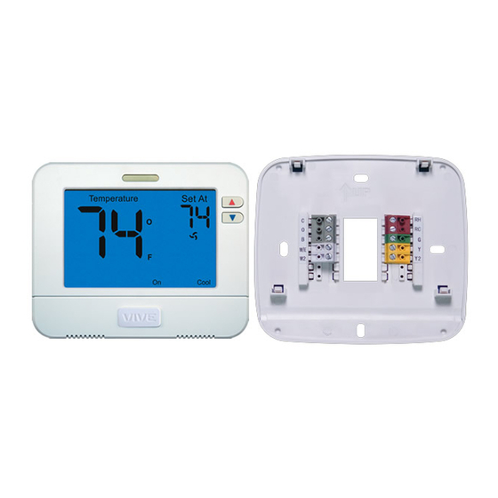
Page 3: Thermostat Quick Reference
THERMOSTAT QUICK REFERENCE Getting to know your thermostat Indicates the current room temperature. Displays the user selectable setpoint temperature. System operation indicators: The COOL, HEAT or FAN icon will display when the COOL, HEAT or FAN is on. NOTE: The compressor delay feature is active if these icons are ashing. -
Page 4: Subbase Installation
SUBBASE INSTALLATION Mercury Notice: Caution: Electrical Hazard All of the our thermostats are mercury free. However, if the Failure to disconnect the product you are replacing power before beginning to contains mercury, dispose of it install this product can cause properly. -
Page 5: Wiring
WIRING Power supply Factory-installed jumper. Remove only when installing on 2-transformer systems Use either O or B terminals for changeover valve Optional 24 VAC common connection when thermostat is hardwired with battery backup mode. Typical 2H/2C system: 1 transformer Typical 2H/2C system: 2 transformer REMOVE JUMPER L1 (HOT) L1 (HOT) -
Page 6: Terminal Designations
WIRING Wiring Warning If you are replacing a thermostat, make note All components of the control of the terminal connections on the thermo- system and the thermostat stat that is being replaced. In some cases the installation must conform to wiring connections will not be color-coded. -
Page 7: Technician Setup Menu
TECHNICIAN SETUP MENU Technician Setup Menu This thermostat has a technician setup menu Con gure the installer options as for easy installer con guration. To setup the desired, using the table below. thermostat for your particular application: Use the keys to change Press and hold &... - Page 8 TECHNICIAN SETUP MENU Tech Setup Steps (Continued from the previous page) Heating Cooling Always On Contractor Call Contractor ºF or ºC Temperature Temperature Operation Light Menu Setup Number Call Number Setpoint Limit Setpoint Limit On or O Select GAS for The display light can Allows you to select Allows you to put you...
- Page 9 TECHNICIAN SETUP MENU Tech Setup Steps (Continued from the previous page) Stages Cooling Fan Beep Heat Pump System Gas Auxiliary of Heat Delay Switch for Heat Pump When any key is When turned on the You can con gure the Gas Auxiliary for Heat You can con gure the The cooling fan delay...
- Page 10 TECHNICIAN SETUP MENU Tech Setup Steps (Continued from the previous page) Staging Delay Humidity Pad UV Lamp IAQ Cell Reminder Satisfy Setpoint Reminder Reminder This feature allows a This will remind the Will remind the user Will remind the user This feature allows delay to occur when user to change the...
-
Page 11: Mounting And Battery Installation
MOUNT THERMOSTAT & BATTERY INSTALLATION Mount Thermostat Align the 4 tabs on the subbase with corresponding slots on the back of the thermostat, then push gently until the thermostat snaps in place. Battery Installation Battery installation is optional if thermostat is hardwired (C terminal connected). On the back of the thermostat insert 2 AA Alkaline batteries (included). -
Page 12: Speci Cations
SPECIFICATIONS Speci cations 41ºF to 95ºF (5ºC to 35ºC) The display range of temperature 44ºF to 90ºF (7ºC to 32ºC) The control range of temperature 1 amp per terminal, 1.5 amp maximum all terminals combined Load rating Display accuracy ± 1ºF Heating is adjustable from 0.2ºF to 2.0ºF Swing (cycle rate or di erential) Cooling is adjustable from 0.2ºF to 2.0ºF...
Need help?
Do you have a question about the TP-N-851 and is the answer not in the manual?
Questions and answers