Advertisement
Quick Links
Installation Manual
Vive Comfort
PO Box 3377
Springfield, MO 65804
Toll Free : 888-776-1427
Web: www.vivecomfort.com
Hours of Operation: M-F 9AM - 6PM Eastern
Thermostat Application Guide
Description
Gas or Oil Heat
Electric Furnace
Heat Pump (No Aux. or Emergency Heat)
Heat Pump (With Aux. or Emergency Heat)
Multi-Stage Systems
Heat Only Systems
Heat Only Systems - Floor or Wall Furnace
Cool Only
Millivolt
Table of Contents
Installation Tips
Thermostat Quick Reference
Wiring
Wiring Diagrams
Features
About The Badge
Technician Setup
Programming Thermostat
Specifications
The display range of temperature ... 41˚F to 95˚F (5˚C to 35˚C)
The control range of temperature.... 44˚F to 90˚F (7˚C to 32˚C)
Swing (cycle rate or differential) ...... Heating is adjustable from 0.2˚ to 2.0˚
Power source ...........................................18 to 30 VAC, NEC Class II, 50/60 Hz
Operating ambient ............................... 32˚F to +105˚F (0˚C to +41˚C)
Operating humidity .............................. 90% non-condensing maximum
Dimensions of thermostat ................. 4.7"W x 4.4"H x 0.8"D
U.S. Registered Trademark. Patents pending
1
Copyright
2015 All Rights Reserved.
Installation Tips
Mount Thermostat
Align the 4 tabs on the subbase with
corresponding slots on the back of the
thermostat, then push gently until the
thermostat snaps in place.
Battery Installation
Battery installation is recommended even if thermostat is hardwired
(C terminal connected). When thermostat is hardwired and batteries
are installed, the thermostat will activate a compressor delay of 5
minutes when the thermostat detects a power outage from the
hardwired power supply.
Important:
High quality alkaline batteries are recommended.
Rechargeable batteries or low quality batteries
do not guarantee a 1-year life span.
Insert 2 AA
Alkaline batteries
(included). High
quality alkaline
batteries are
recommended.
3
TP-P-705
Power Type
Battery Power
Hardwire (Common Wire)
Yes
Hardwire (Common Wire) with
Yes
Battery Backup
Yes
No
A trained, experienced
No
technician must install this
Yes
product.
Yes
Carefully read these
Yes
instructions. You could damage
Yes
this product or cause a
hazardous condition if you fail to
Page
follow these instructions.
2-3
4-5
Una version en espanol de este
6
manual se puede descargar en
7-8
la pagina web de la compania.
9
10
11-13
13-16
Cooling is adjustable from 0.2˚ to 2.0˚
for hardwire
Battery power from 2 AA Alkaline
batteries
FAN
ON AUTO
online.
Installation Tips
Wall Locations
The thermostat should be installed approximately 4 to 5 feet above the
floor. Select an area with average temperature and good air circulation.
Installation Tip
Pick an installation location that is easy for
the user to access. The temperature of the
location should be representative of the
building.
Subbase Installation
Horizontal Mount
Vertical Mount
For vertical mount put one screw on the top
and one screw on the bottom.
For horizontal mount put one screw on the
left and one screw on the right.
Rev. CH1612
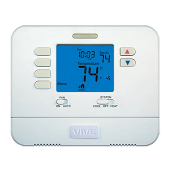
Thermostat Quick Reference
Getting to know your thermostat
SYSTEM
COOL OFF HEAT
Simple
operating
instructions
are found
on the back
of the
battery
door.
Do not install
thermostat in locations:
• Close to hot or cold air ducts
• That are in direct sunlight
• With an outside wall behind
the thermostat
• In areas that do not require
conditioning
• Where there are dead spots
or drafts
(in corners or behind doors)
• Where there might be
concealed chimneys or
pipes
Installation Tip:
Electrical Hazard
Failure to disconnect the power before
beginning to install this product can
cause electrical shock or equipment
damage.
Mercury Notice
All of our products are mercury free.
However, if the product you are
replacing contains mercury, dispose of
it properly. Your local waste
management authority can give you
instructions on recycling and proper
disposal.
FAN
SYSTEM
ON AUTO
COOL OFF HEAT
LCD Display
Glow in the dark light button
Fan Switch
System Switch
Easy change battery door
Temperature Setpoint Buttons
User Buttons
2
4
Advertisement

Related Manuals for Vive Comfort TP-P-705


Summary of Contents for Vive Comfort TP-P-705
- Page 1 Installation Manual Installation Tips TP-P-705 Wall Locations The thermostat should be installed approximately 4 to 5 feet above the floor. Select an area with average temperature and good air circulation. Vive Comfort Do not install PO Box 3377 thermostat in locations: Springfield, MO 65804 •...
- Page 2 Thermostat Quick Reference Wiring Wiring Getting to know your thermostat Caution: If you are replacing a thermostat, Electrical Hazard Sun Mon Tue Wed Thu Fri Sat make note of the terminal connections on the thermostat Tech Set Failure to disconnect the power Next Step that is being replaced.
- Page 3 Wiring Diagrams Wiring Diagrams Power supply Power supply Factory-installed jumper. Remove only when installing on 2-transformer systems Factory-installed jumper. Remove only when installing on 2-transformer systems Use either O or B terminals for changeover valve Use either O or B terminals for changeover valve Use a small piece of wire (not supplied) to connect W and Y terminals Use a small piece of wire (not supplied) to connect W and Y terminals Set fan operation setting to Electric...
- Page 4 Tech Settings & Programming Programming Programming Set Time All of our programmable thermostats are shipped with an With system switch set to OFF, press the MENU button energy saving pre-program. You can customize this default SET TIME Press program by following the steps on page 16. Day of the week will be flashing.