
Related Manuals for Gree VIR09HP115V1A


Summary of Contents for Gree VIR09HP115V1A
-
Page 1: Installation Manual
HIGH-WALL DUCTLESS AIR CONDITIONING & HEATING SYSTEM INSTALLATION MANUAL Models: VIR18HP230V1A VIR09HP115V1A VIR24HP230V1A VIR12HP115V1A VIR30HP230V1A VIR09HP230V1A VIR36HP230V1A VIR12HP230V1A... -
Page 2: Table Of Contents
Thank you for choosing a Vireo Heat Pump for your customer. Please read this installation manual carefully before installing and starting up the Vireo System.Take a moment to fill out the product and installation form on the back cover. Retain both the manual and installation record for future reference. Table of Contents Safety Precautions . -
Page 3: Safety Precautions
SAFETY PRECAUTIONS Please read the following before operation. Recognize safety information. This is the safety-alert symbol. When you see this symbol on the unit and in instructions or manuals, be alert to the potential for personal injury. Understand these signal words: DANGER, WARNING, and CAUTION. These words are used with the safety-alert symbol. -
Page 4: Electrical Shock Hazard
SAFETY PRECAUTIONS C UTION • The unit should be installed and serviced only by trained, qualified installers and service technicians. Untrained personnel can perform basic maintenance functions such as cleaning coils.All other operations should be performed by trained service personnel. •... -
Page 5: Nomenclature
NOMENCLATURE Example: VIR24HP230V1AH 24 HP 230V 1 Series Designation Product Type S - System CROWN O - Outdoor units H - Indoor High Wall TERRA D - Indoor Duct VIREO C - Indoor Cassette F - Indoor Floor/Ceiling Cooling Capacity 09 - 9,000 BTUH 12 - 12,000 BTUH Revision Level... -
Page 6: System Requirements
SYSTEM REQUIREMENTS PIPE SIZE in (mm) Unit Size Voltage Liquid Line Suction/Gas Line (BtuH) 3/8 (9.5) 9,000 115v - 1ph 60hz 1/4 (6) 1/2 (12) 12,000 115v - 1ph 60hz 1/4 (6) 3/8 (9.5) 9,000 208/230v - 1ph 60hz 1/4 (6) 1/2 (12) 12,000 208/230v - 1ph 60hz... -
Page 7: Suggested Tools
SUGGESTED TOOLS • Standard Wrench • Adjustable/Crescent Wrench • Torque Wrench • Hex Keys or Allen Wrenches • Drill & Drill Bits • Hole Saw • Pipe Cutter • Screw drivers (Phillips & Flat blade) • Manifold and Gauges • Level •... -
Page 8: Part Names
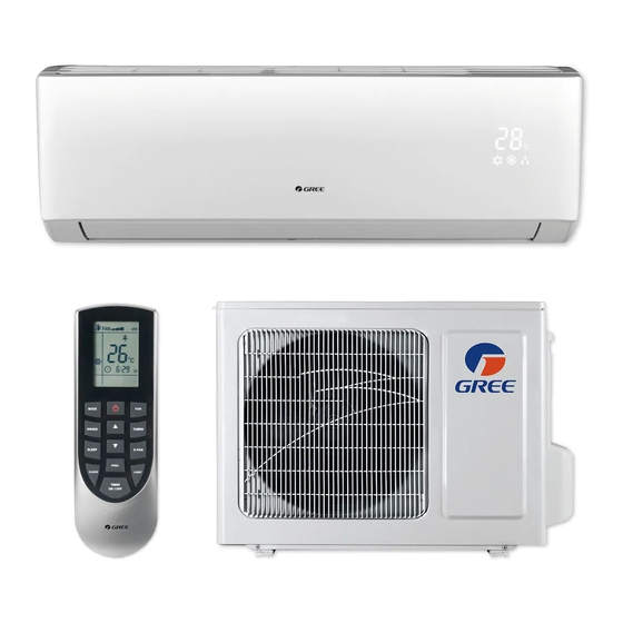
PART NAMES Air inlet Indoor unit Air outlet Part Name 1. Front Panel 2. Aux. Button 3. Filter 4. Horizontal Louver 5. Remote Controller 6. Inter-Connection Wire 7. Drain Hose 8. Refrigerant Lines Air inlet Outdoor unit Air outlet... -
Page 9: Installation Site Instructions
INSTALLATION SITE INSTRUCTIONS Indoor Unit Select a site that allows for the following: 1. Ensure the installation complies with the installation minimum dimensions (defined below) and meets the minimum and maximum connecting piping length and maximum change in elevation as defined in the System Requirements section. 2. - Page 10 INSTALLATION SITE INSTRUCTIONS Outdoor Unit Select a site that allows for the following: 1. Outdoor location meets all minimum installation clearances defined below. 2. Sound from outdoor unit will not annoy neighbors. 3. All connections can be easily made to indoor unit. 4.
-
Page 11: Indoor Unit Installation
INDOOR UNIT INSTALLATION INDOOR UNIT DIMENSIONS in (mm) Model 33.4 11.4 VIR09HP115V1A (848) (290) (208) 33.4 11.4 VIR12HP115V1A (848) (290) (208) 33.4 11.4 VIR09HP230V1A (848) (290) (208) 33.4 11.4 VIR12HP230V1A (848) (290) (208) 38.2 11.8 VIR18HP230V1A (970) (300) (224) 42.4 12.8... -
Page 12: Indoor Unit Installation
INDOOR UNIT INSTALLATION Mounting Bracket Diagrams and Dimensions 4 5/8 21 3/8 7 1/4 2 1/4 2 1/4 1 3/8 1 3/8 9,000 and 12,000 Units 7 1/4 2 1/4 2 1/4 1 1/2 1 1/2 7 1/2 5 1/2 18,000 Unit 8 1/9 7 3/8... -
Page 13: Outdoor Unit Installation
OUTDOOR UNIT INSTALLATION Outdoor Unit Dimensions OUTDOOR UNIT DIMENSIONS in (mm) Model 33.4 21.3 11.3 21.3 12.6 VIR09HP115V1A (842) (537) (285) (537) (318) 21.3 11.3 21.3 33.4 12.6 VIR12HP115V1A (842) (537) (285) (537) (318) 33.4 21.3 11.3 21.3 12.6 VIR09HP230V1A... - Page 14 OUTDOOR UNIT INSTALLATION Ground Pad or Wall Hangers Installation 1. Determine proper location for outdoor unit. 2. Follow all instructions provided by manufacturer for installing wall hangers or ground pad. 3. Verify the wall hangers or ground pad can safely support the weight of the outdoor unit. 4.
-
Page 15: Piping Installation
PIPING INSTALLATION Refrigerant Piping Drill Hole in Wall If indoor unit refrigerant piping is going to exit from the rear: 1. It is recommended that the refrigerant pipe flare connectors extend through the wall to the outside. In some situations field-fabricated piping extensions will be required to extend the indoor unit refrigerant flare connections to the outside of the wall. - Page 16 PIPING INSTALLATION Refrigerant Piping C UTION Use refrigeration grade piping ONLY. Uses of other piping will void the Manufacturer’s Warranty. Piping Preparation: 1. Do not open service valves or remove protective caps on pipes until all connections are made. 2. Keep tubing free of dirt, sand, moisture and contaminants. 3.
- Page 17 PIPING INSTALLATION Refrigerant Piping Piping Connections to Indoor Unit (con’t): 4. Properly align piping and tighten flare nut using a standard wrench and a torque wrench as shown in figure to the below. Carefully tighten flare nuts to correct torque level referring to the Torque Table on page 15.
- Page 18 PIPING INSTALLATION How to Relocate Drain Hose from Left to Right Side (if required) 1. Locate drain plug on right side of the drain tray. Firmly grab it and remove from drain tray. Left Right 2. Locate drain tube on the left side of drain tray. Twist drain tube counter-clockwise and gently pull to remove from the drain tray.
-
Page 19: Power And Wiring Installation
POWER AND WIRING INSTALLATION System Wiring Diagrams Indoor Unit Outdoor Unit 9,000 and 12,000 BtuH (115V Models) 9,000 and 12,000 BtuH (230V Models) 18,000 and 24,000 BtuH (230V Models) 30,000 and 36,000 BtuH (230V Models) - Page 20 POWER AND WIRING INSTALLATION Indoor Unit Wire Connections W RNING Disconnect all electrical power to indoor and outdoor units including disconnects, fuses and circuit breakers. Lockout and tag all disconnect switches. 1. Open front cover of indoor unit and remove field wiring terminal block cover. 2.
-
Page 21: Power And Wiring Installation
POWER AND WIRING INSTALLATION Outdoor Unit Wire Connections Disconnect all electrical power to unit including disconnects, fuses and circuit breakers. Lockout and tag all disconnect switches. 1. Remove the service panel on right side of the outdoor unit. 2. Insert interconnecting wires and main power wires through the wire holes on conduit mounting bracket. -
Page 22: Testing And Inspection
TESTING AND INSPECTION Leaking Test 1. Connect the charging hose of the manifold valve to charge the end of the low-pressure valve. 2. Add dry nitrogen to a pressure of 200 lbs.Tightly close both high- and low-pressure valves. 3. Leak-test flare fittings with soap bubbles. If no leak is detected, release nitrogen. C UTION Use vacuum pump, rather than refrigerant, to discharge air when installing the unit. -
Page 23: Additional Charge
TESTING AND INSPECTION Vacuum Procedure (con’t) 7. Confirm that manifold valves are closed and disconnect the vacuum pump. 8. Open the service valves to the fully ‘back-seat’ position to let the refrigerant flow to the indoor unit and balance the pressure in system. Important: Do not allow air to enter the connection pipe when removing the hose. -
Page 24: Testing And Inspection
TESTING AND INSPECTION Outdoor Oil Return Bend Oil return bend When the outdoor unit is more than 30 feet above the indoor unit, an oil return bend must be added for every 20 feet of connection pipe. Indoor Oil return bend Condensate Drain Pipe Testing Carefully and slowly add 8-10 ounces of water to the indoor unit drain pan. -
Page 25: Troubleshooting
TROUBLESHOOTING PROBLEM CAUSE/SOLUTION System does not restart. Cause: The system has a built-in three-minute delay to prevent short and/or rapid cycling of the compressor. Solution: Wait three minutes for the protection delay to expire. Indoor unit emits unpleasant odor Cause: Typically unpleasant odors are the result of mold or mildew forming on when started the coil surfaces or the air filter. - Page 26 TROUBLESHOOTING PROBLEM CAUSE/SOLUTION Water leaking from the indoor Cause: While it is normal for the system to generate condensate water in cooling unit into the room. mode, it is designed to drain this water via a condensate drain system to a safe location. Solution: If water is leaking into the room, it may indicate one of the following.
-
Page 27: Diagnostic Codes
DIAGNOSTIC CODES Troubleshooting The Vireo System has onboard diagnostics. The outdoor unit will provide status indicators. The indoor wall unit and remote controller will display error codes. The following is a summary of the codes with explanation: Indoor Unit Outdoor Unit Indicators Malfunction Name Possible Causes &... - Page 28 DIAGNOSTIC CODES Outdoor Unit Indicators Indoor Unit Malfunction Name Possible Causes Display Yellow Indoor Ambient Temperature 1) Loose or bad connection between sensor and control board. Sensor Malfunction 2) Indoor ambient temperature sensor damaged. 3) Control board malfunction. Indoor Coil Temperature 1) Loose or bad connection between sensor and control board.
-
Page 29: Diagnostic Codes
DIAGNOSTIC CODES Outdoor Unit Indicators Indoor Unit Malfunction Name Possible Causes Display Yellow IPM Module Protection 1) IPM module over heating. 4 flashes 2) Improper or Low voltage at the IPM module. 3) IPM module malfunction. 1 sec Off Indoor DC Fan Motor 1) Loose connections between fan motor and control board Malfunction 2) Fan motor or blower wheel bearings malfunction. -
Page 30: Care And Cleaning
CARE AND CLEANING W RNING Take notice of the following items before cleaning the Vireo Indoor wall unit. • To avoid electric shock or injury, do not attempt to clean the unit unless it has been turned off and disconnected from the main power supply. •... - Page 31 UNIT INFORMATION Outdoor Unit: Model No. Serial No. Indoor Unit: Model No. Serial No. INSTALLATION INFORMATION Date Installed: DEALERSHIP/INSTALLER INFORMATION Company Name: Address: Phone Number: Technician Name: Gree Electric Appliances, Inc ©2015 Cat No: DFS-VIR-HP-1IN...
Need help?
Do you have a question about the VIR09HP115V1A and is the answer not in the manual?
Questions and answers